
A sensor installation structure for building construction based on fiber grating

A technology of optical fiber grating and building construction, which is applied in the direction of transmitting sensing components, converting sensor output, and instruments by using optical devices, which can solve problems such as wasting time and increasing workload, and achieves reducing workload, saving time, and convenient fixing Effect

Active Publication Date: 2021-01-12
齐贺
View PDF7 Cites 0 Cited by
  • Summary
  • Abstract
  • Description
  • Claims
  • Application Information

AI Technical Summary

Problems solved by technology

[0005] The purpose of the present invention is to provide a sensor installation structure based on optical fiber gratings for building construction, which has the advantages of conveniently fixing sensors and wires and saving time, and solves the problem that the wires connected to the sensor also need to be fixed on the wall by nails It will increase the workload, and the buttons need to be removed one by one after the measurement, which is a waste of time

Method used


Image

  • A sensor installation structure for building construction based on fiber grating
  • A sensor installation structure for building construction based on fiber grating
  • A sensor installation structure for building construction based on fiber grating

Examples


Embodiment Construction

[0016] The following will clearly and completely describe the technical solutions in the embodiments of the present invention with reference to the accompanying drawings in the embodiments of the present invention. Obviously, the described embodiments are only some, not all, embodiments of the present invention. Based on the embodiments of the present invention, all other embodiments obtained by persons of ordinary skill in the art without making creative efforts belong to the protection scope of the present invention.

[0017] In the description of the present invention, it should be noted that the terms "upper", "lower", "inner", "outer", "front end", "rear end", "both ends", "one end", "another end" The orientation or positional relationship indicated by etc. is based on the orientation or positional relationship shown in the drawings, and is only for the convenience of describing the present invention and simplifying the description, rather than indicating or implying that ...


PUM


Abstract

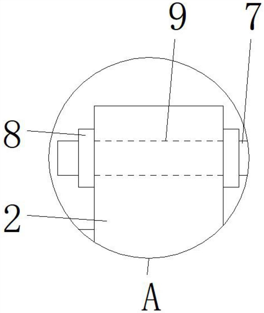
The invention discloses a sensor installation structure used for building construction based on a fiber bragg grating. The structure comprises a first fixing block, a fiber bragg grating sensor body,a bolt and a cross rod. Two ends of the fiber bragg grating sensor body are provided with second fixing blocks. Second through holes are arranged in bottom ends of the two second fixing blocks. A screw hole is arranged in a front surface of the first fixing block. The bolt penetrates through the second through holes and is screwed into the screw hole. First through holes are arranged in the top ends of the two second fixing blocks. One end of the cross rod penetrates through the first through hole, and a thread is arranged at one end of the cross rod. One end of the cross rod matches with thefirst through hole, two nuts installed at one end of the cross rod in a screw installation mode are attached to two sides of the top ends of the second fixing blocks. A hanging ring is fixed to a bottom end of the cross rod, and the two ends of the fiber bragg grating sensor body are connected with wires. In the invention, the sensor and the wires can be conveniently fixed and time is saved.

Description

technical field [0001] The invention relates to the technical field of installation of optical fiber grating sensors, in particular to a sensor installation structure for building construction based on optical fiber gratings. Background technique [0002] Fiber Bragg grating sensor is a kind of fiber optic sensor. The sensing process based on fiber Bragg grating is to obtain sensing information through the modulation of fiber Bragg wavelength by external physical parameters. It is a wavelength modulation fiber optic sensor. direct measurement. [0003] Reinforcement and underpinning in the reconstruction of existing building structures first reinforce the existing load-bearing structure and then perform underpinning processing. When renovating the existing building structure, it is necessary to monitor the relevant data of the load-bearing system of the building, which can be carried out through fiber optic grating sensors. monitor. [0004] The existing fiber grating sens...

Claims


Application Information

Patent Timeline
Patent Type & Authority Patents(China)
IPC IPC(8): G01D5/353
CPCG01D5/35316
Inventor 齐贺
Owner 齐贺
Learn More