
Convenient-to-repair fabricated steel structure beam-column joint connection structure and fabricating method thereof

A beam-column joint and connection structure technology, applied in building construction, construction, etc., to achieve the effect of easy control of precision and quality, simple structure, and accelerated construction progress

Inactive Publication Date: 2019-11-26
CHANGAN UNIV
View PDF6 Cites 9 Cited by
  • Summary
  • Abstract
  • Description
  • Claims
  • Application Information

AI Technical Summary

Problems solved by technology

[0004] The present invention proposes an assembled steel structure beam-column joint connection structure and its assembly method that are easy to repair, and its purpose is to overcome the defects of the prior art to solve the problem of easy repair of post-earthquake joint damage

Method used


Image

  • Convenient-to-repair fabricated steel structure beam-column joint connection structure and fabricating method thereof
  • Convenient-to-repair fabricated steel structure beam-column joint connection structure and fabricating method thereof
  • Convenient-to-repair fabricated steel structure beam-column joint connection structure and fabricating method thereof

Examples


Embodiment 1

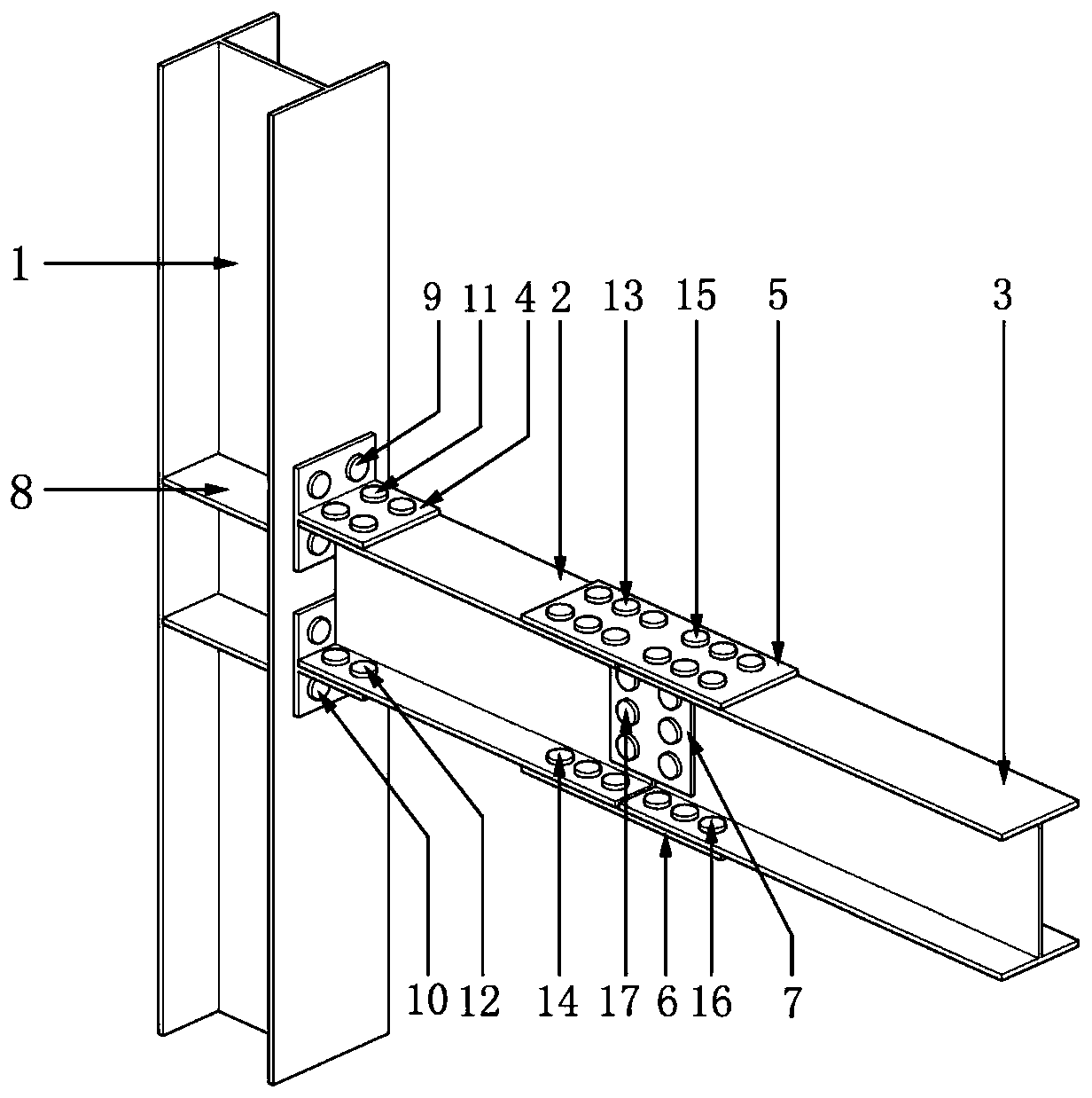
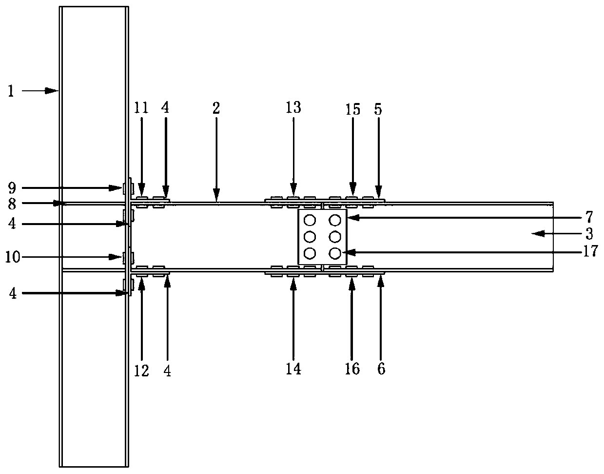
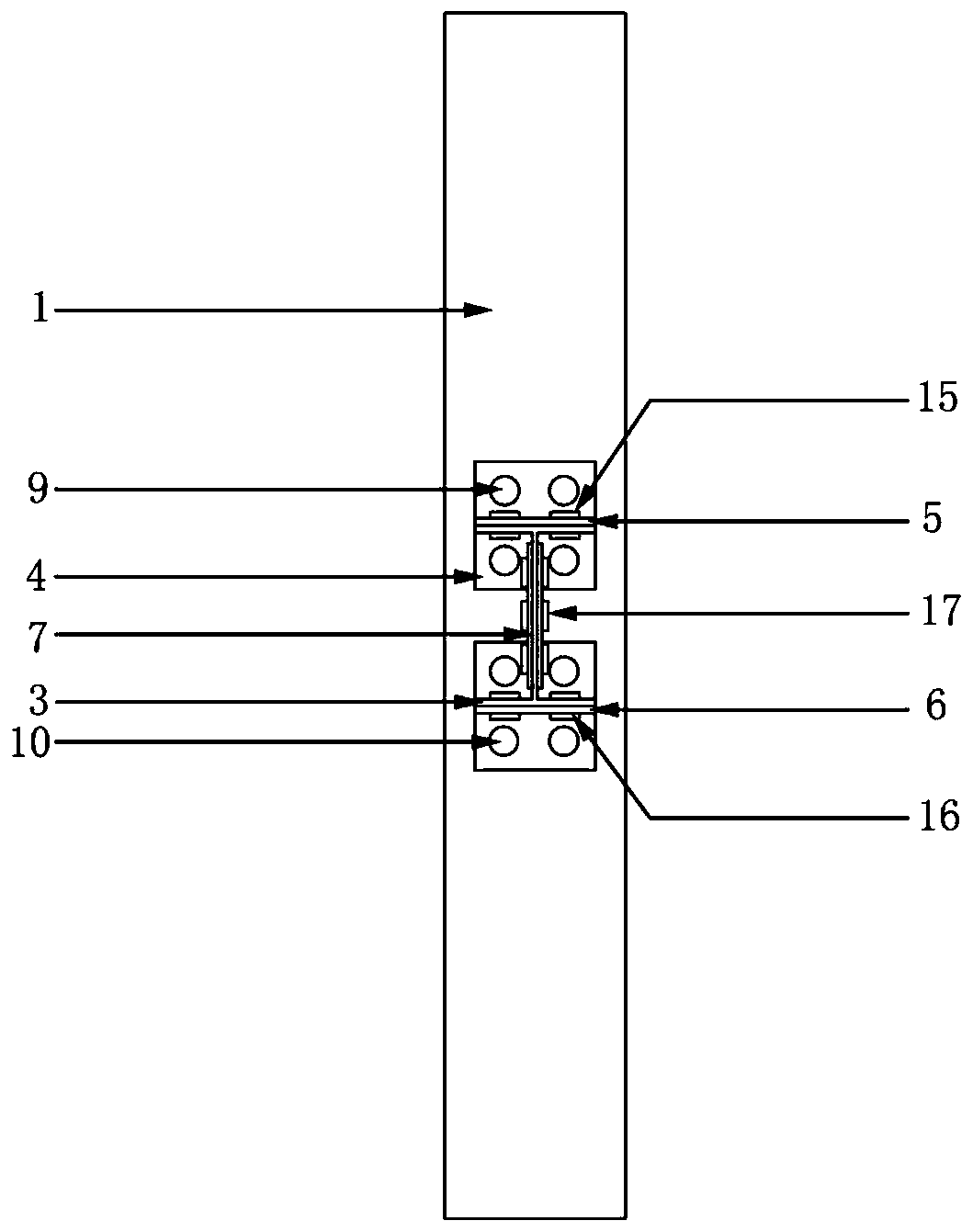
[0040] refer to Figure 1 to Figure 6, a prefabricated steel structure beam-column joint connection structure that is easy to repair, consists of H-shaped steel columns with stiffeners, H-shaped steel energy-dissipating beam sections 2, H-shaped steel ordinary beam sections 3, and connecting devices for the three. Both the H-shaped steel energy-dissipating beam section 2 and the H-shaped steel ordinary beam section 3 are composed of H-shaped steel. The H-shaped steel column with stiffeners is welded by the H-shaped steel column 1 and two stiffeners 8, the thickness of the stiffeners 8 is not less than the thickness of the flange of the H-shaped steel energy-dissipating beam section 2, and the width of the stiffeners 8 is greater than that of the H-shaped steel consumption The width of the flange of the energy-dissipating beam section 2, and the two stiffeners 8 are respectively located on the same level as the two flanges of the H-shaped steel energy-dissipating beam section 2...

Embodiment 2

[0052] Such as Figure 7 As shown, the difference between this embodiment and Embodiment 1 is that: the flange of the H-shaped steel energy-dissipating beam section 2 is provided with a dog-bone weakening area 18 .

Embodiment 3

[0054] Such as Figure 8 As shown, the difference between this embodiment and Embodiment 1 lies in that: the web of the H-shaped energy-dissipating beam section 2 is provided with a web hole weakening area 19 .

[0055] A large number of studies have shown that weakening the section of the beam member can form a weak zone on the beam member, so that a plastic ratio can be formed in the weakened zone, which can improve the rotation capacity and energy dissipation capacity of the node. The common weakening section method is in the flange Set a dog bone weakening area or open a hole at the web. Therefore, the node proposed by the present invention can be provided with a dog-bone weakened area at the flange of the H-shaped steel energy-dissipating beam section or with an opening area at the web according to actual needs.


PUM


Abstract

The invention discloses a convenient-to-repair fabricated steel structure beam-column joint connection structure and a fabricating method thereof. The convenient-to-repair fabricated steel structure beam-column joint connection structure comprises an H-shaped steel column, an H-shaped steel energy-consuming beam segment and an H-shaped steel ordinary beam segment, the H-shaped steel column is fixedly connected with the H-shaped steel energy-consuming beam segment through a T-shaped connecting part, an upper flange of the H-shaped steel energy-consuming beam segment and an upper flange of the H-shaped steel ordinary beam segment are fixedly connected through an upper flange connecting plate, a lower flange of the H-shaped steel energy-consuming beam segment and a lower flange of the H-shaped steel ordinary beam segment are fixedly connected through a lower flange connecting plate, and a web of the H-shaped steel energy-consuming beam segment and a web of the H-shaped steel ordinary beamsegment are fixedly connected through a web connecting plate. Destroying possibly occurring in a column or joint area is transferred and limited in the locally replaceable H-shaped steel energy-consuming beam segment, by utilizing plastic deformation energy consumption of the H-shaped steel energy-consuming beam segment, the purpose of protecting the column and a joint can be achieved, and afteran earthquake, the anti-seismic toughness and the use function of the structure can be quickly restored only by replacing the locally damaged beam segment.

Description

technical field [0001] The invention belongs to the technical field of construction, and in particular relates to an assembled steel structure beam-column joint connection structure and an assembly method thereof which are easy to repair. Background technique [0002] At present, in the field of civil engineering construction, as far as the building structure is concerned, the concrete structure is still the main structure, and it is constructed by pouring in situ, which not only causes environmental pollution and serious waste of materials, but also affects many aspects such as product quality. Changing the production mode of the traditional construction industry and developing green buildings is the future development trend. The prefabricated steel structure building has the advantages of standardized design, factory production, assembly construction, integrated decoration, and information management, and has become one of the important development directions of green buil...

Claims


Application Information

Patent Timeline
Patent Type & Authority Applications(China)
IPC IPC(8): E04B1/24E04B1/58
CPCE04B1/2403E04B2001/2406E04B2001/2415E04B2001/2418
Inventor 雷拓李坤刘宜杨吉东郭绪新王沁怡
Owner CHANGAN UNIV
Learn More