Eureka AIR delivers breakthrough ideas for toughest innovation challenges, trusted by R&D personnel around the world.

Fire hose connector

A fire hose and joint technology, applied in fire rescue and other directions, can solve problems such as water waste, increase interface pressure, loosening, etc., to avoid water waste, increase tightness, and improve practicability.

Inactive Publication Date: 2019-11-26
江苏泰华消防电气设备有限公司
View PDF8 Cites 0 Cited by
  • Summary
  • Abstract
  • Description
  • Claims
  • Application Information

AI Technical Summary

Problems solved by technology

[0005] The present invention aims to solve the problem that the structure design of the existing fire hose joint is single. When fire rescue is needed in an emergency, it is impossible to adjust the connection distance between the interface and the water source according to the actual fire rescue situation to achieve the best water spraying distance. It will cause real inconvenience in actual use. At the same time, due to the huge water pressure when the existing fire hose connector is spraying water, the connection between the interface and the other end will be loosened to varying degrees, which will cause water damage in the later stage. To solve the problems of waste and leakage, a fire hose joint is provided. By setting spiral threads, movable screws, stretching strips, limit strips and fixing hooks, the structure of the device is stable, and the interface can be connected to the external connection through movable screws. When increasing the pressure on the interface, it can further increase the tightness of the connection between the interface and the external connection in addition to the rubber sheet, so as to avoid the water waste and leakage caused by different degrees of looseness, and the rubber sheet can When connecting the interface with the external connection, increase the connection density with the external connection to avoid loosening under huge water pressure

Method used


Image

  • Fire hose connector
  • Fire hose connector
  • Fire hose connector

Examples


Embodiment

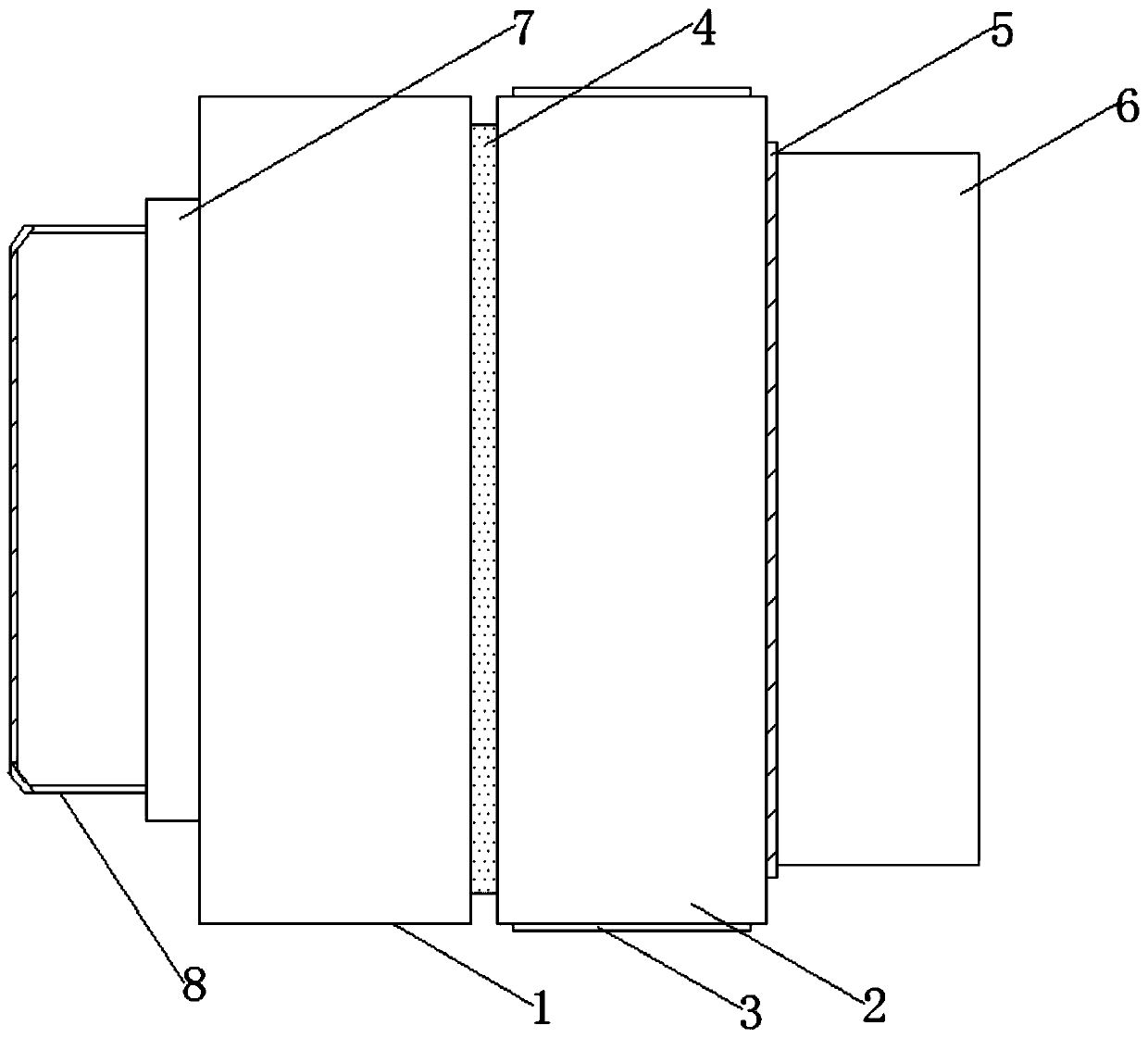
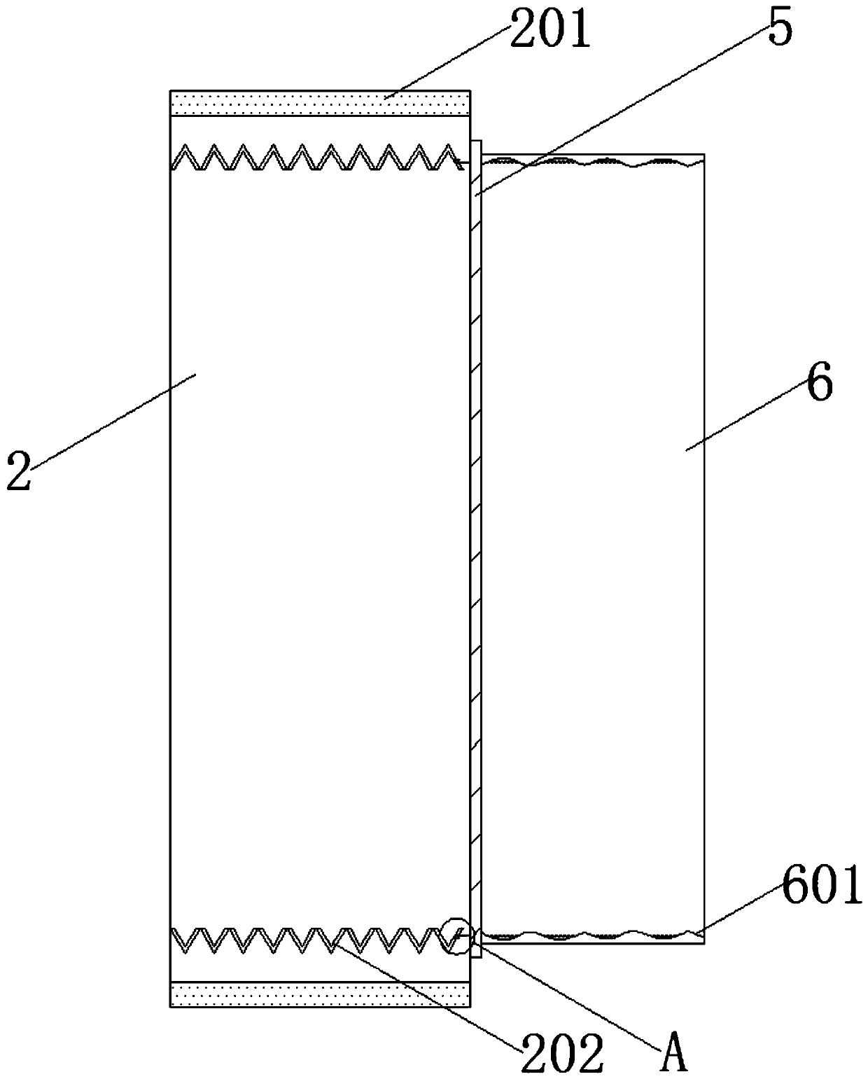
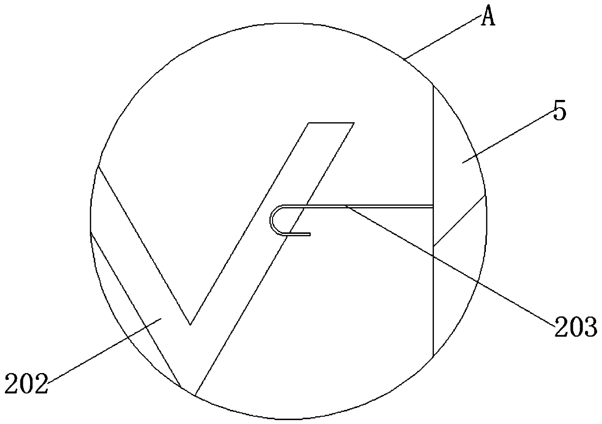
[0024] Refer to Figure 1-4 ,

[0025] The fire hose joint provided by this embodiment includes a joint shaft 1, a connecting housing 2 and a partition 3. The connecting housing 2 is located on one side of the joint shaft 1, and the partitions 3 are respectively located on the side of the connecting housing 2. On one side, one side of the connecting housing 2 is provided with a connecting groove 4, and the connecting housing 2 is connected to the joint shaft 1 through the connecting groove 4, and one side of the connecting housing 2 is fixedly connected with a connecting plate 5. An interface 6 is fixedly connected to one side, a reinforcing plate 7 is fixedly connected to one side of the joint shaft body 1, and a rotating disk 8 is fixedly connected to one end of the reinforcing plate 7.

[0026] Further, the inner edge of the connecting shell 2 is provided with a limiting strip 201, and one side of the limiting strip 201 protrudes 1.2 cm from the inner edge of the connecting she...


PUM


Abstract

The invention provides a fire hose connector, and belongs to the technical field of fire protection. The fire hose connector comprises a connector shaft body, a connecting shell and a partition plate,wherein the connecting shell is located on one side of the connector shaft body, the partition plate is located on one side of the connecting shell, one side of the connecting shell is provided witha connecting groove, and the connecting shell is connected with the connector shaft body through the connecting groove; one side of the connecting shell is fixedly connected with a connecting plate, one side of the connecting plate is fixedly connected with an interface, and one side of the connector shaft body is fixedly connected with a reinforcing plate. With a stable structure, the fire hose connector can increase the pressure on the interface when the interface is connected with an external connecting part through a movable screw, so that the fire hose connector can further increase the tightness when the interface is connected to the external connecting part outside a rubber sheet, the waste and leakage of water source caused by different degrees of looseness can be avoided, and theconnection density of the external connecting part can be increased when the interface is connected with the external connecting part through the rubber sheet, so as to avoid the looseness under the huge water pressure.

Description

Technical field [0001] The invention relates to the technical field of fire protection, in particular to a fire hose joint. Background technique [0002] "Fire protection" means to eliminate hidden dangers and prevent disasters (that is, to prevent and solve the general term of man-made, natural and accidental disasters that people encounter in life, work, and study). Of course, the narrow meaning is in the early stage of people's understanding: (extinguish) The meaning of fire, fire hose is a hose used to transport high-pressure water or foam and other flame-retardant liquids, while the fire hose is lined with rubber, the outer surface is wrapped with linen fabric, and the advanced fire hose is made of polyurethane, etc. It is made of polymer material and has metal joints at both ends of the fire hose. You can connect another hose to extend the distance or connect a nozzle to increase the liquid jet pressure. [0003] However, the existing fire hose joint structure design is sing...

Claims


Application Information

Patent Timeline
IPC IPC(8): A62C33/04
CPCA62C33/04
Inventor 杨红梅张文华陈凤
Owner 江苏泰华消防电气设备有限公司
Why Eureka
Eureka Blog
Learn More