
Exposure control method and device for all-around camera and radar synchronization, medium and equipment

An exposure control and radar technology, applied in the exposure control field of the surround view camera and the radar synchronization, can solve the problems of high cost, complicated control, inability to configure the exposure time of the camera flexibly, etc., and achieves the effect of strong applicability, flexible operation, and improved accuracy.

Pending Publication Date: 2019-11-22
CHANGSHA XINGSHEN INTELLIGENT TECH CO LTD
View PDF9 Cites 2 Cited by
  • Summary
  • Abstract
  • Description
  • Claims
  • Application Information

AI Technical Summary

Problems solved by technology

This method has high requirements for lidar control (such as the need to accurately monitor the rotation position of the lidar), and even requires customization, high cost and complicated control; moreover, there are certain limitations in the exposure control of the camera, which cannot be based on Use the environment to flexibly configure the exposure time of the camera

Method used


Image

  • Exposure control method and device for all-around camera and radar synchronization, medium and equipment
  • Exposure control method and device for all-around camera and radar synchronization, medium and equipment
  • Exposure control method and device for all-around camera and radar synchronization, medium and equipment

Examples


Embodiment Construction

[0027] The present invention will be further described below in conjunction with the accompanying drawings and specific embodiments.

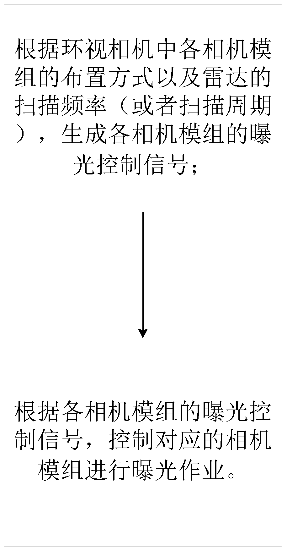
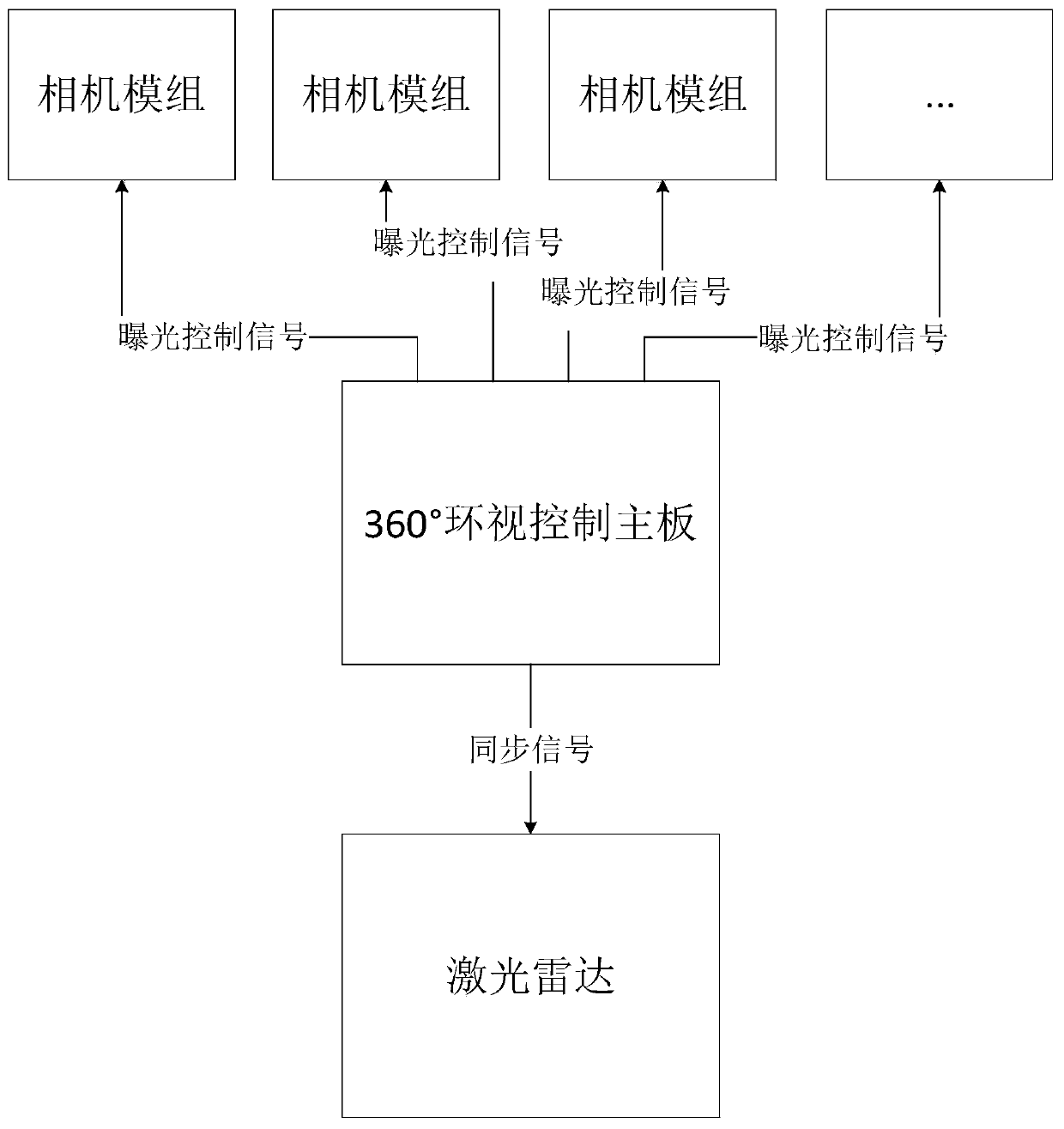
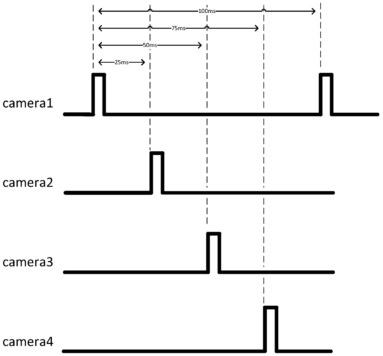
[0028] Such as figure 1 As shown, the exposure control method of the surround-view camera and radar synchronization of the present embodiment is suitable for unmanned vehicles, unmanned delivery vehicles, etc., wherein the surround-view camera adopts a 360-degree surround-view camera, including a plurality of fixed camera modules (cameras) ), a plurality of camera modules are arranged in the circumferential direction to achieve 360-degree look-around image acquisition; the radar adopts laser radar, which can rotate relative to the look-around camera; the specific exposure control method includes the following steps:

[0029] S01. Generate exposure control signals for each camera module according to the layout of each camera module in the surround-view camera and the scanning frequency (or scanning period) of the radar;

[0030] S02. According ...


PUM


Abstract

The invention, which belongs to the technical field of unmanned driving, discloses an exposure control method and device for all-around camera and radar synchronization, a medium and equipment, thereby solving a technical problem that the all-around camera and radar synchronization can not be flexibly configured. To be specific, according to an arrangement mode of all camera modules in the all-around camera and the scanning frequency of the radar, an exposure control signal of each camera module is generated; and then the corresponding camera module is controlled to perform the exposure operation according to the exposure control signals of each camera module. Therefore, the method has advantages of flexible operation, low cost, and high applicability and the like.

Description

technical field [0001] The present invention mainly relates to the technical field of unmanned driving, in particular to an exposure control method, device, medium and equipment for synchronizing a surround-view camera and a radar. Background technique [0002] Obstacle detection in the driving environment of unmanned vehicles is one of the key technologies of the environment perception system of unmanned vehicles. At this stage, the sensors installed on the driverless car are usually used to collect and analyze the two-dimensional images and three-dimensional distance data around the car in real time during driving, and transmit the data to the control system of the driverless car to control the driverless car. Drive the car to take control. Vision cameras and LiDAR are the two most commonly used ranging sensing elements today. The visual camera monitors the objects around the car in real time, and at the same time calculates the distance between the object and the vehicl...

Claims


Application Information

Patent Timeline
Patent Type & Authority Applications(China)
IPC IPC(8): G01S17/93G01S7/497
CPCG01S7/497
Inventor 罗增渠军李世星
Owner CHANGSHA XINGSHEN INTELLIGENT TECH CO LTD
Learn More