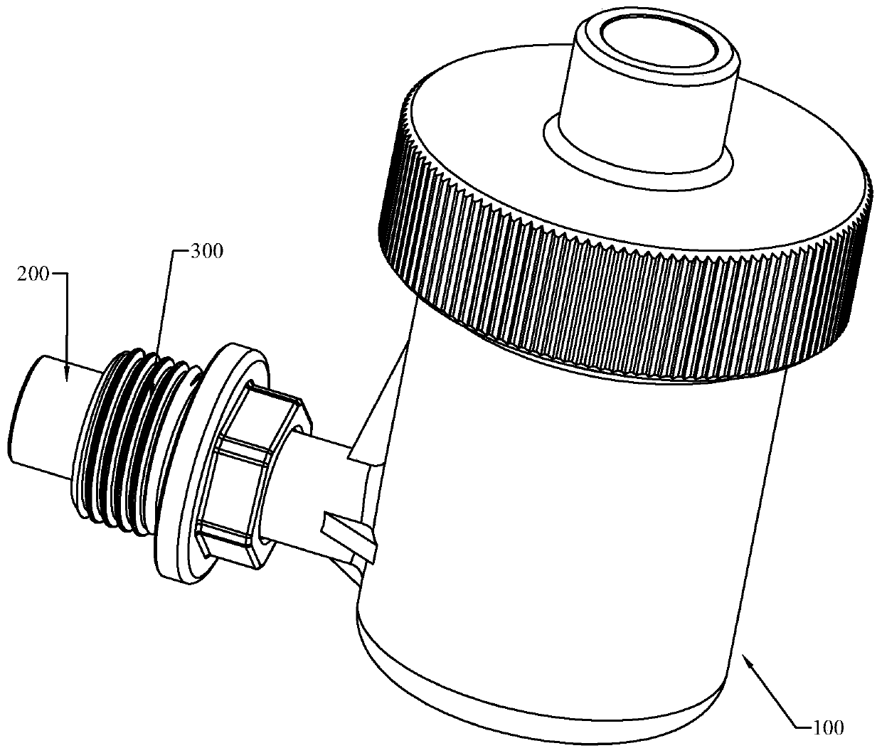
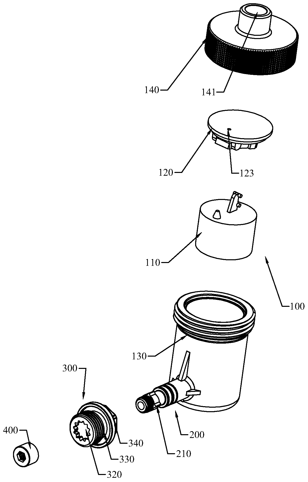
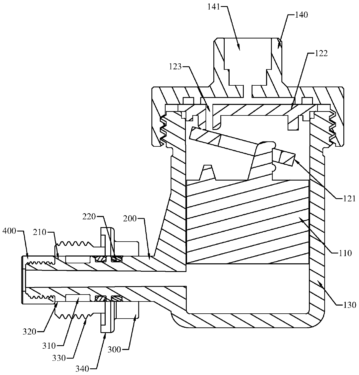
Pipe joint and exhaust valve

A technology for exhaust valves and pipe joints, applied to pipes/pipe joints/fittings, pipe components, valve details, etc., can solve the problems of difficult pressure, low efficiency, and low efficiency of pressure testing, and achieve good exhaust effect and high efficiency high effect

Pending Publication Date: 2019-11-22
屋联智能山东集团股份有限公司
View PDF0 Cites 0 Cited by
  • Summary
  • Abstract
  • Description
  • Claims
  • Application Information

AI Technical Summary

Problems solved by technology

It can be seen that during the pipeline pressure test, the step of venting is very necessary, otherwise it will cause difficulty in suppressing pressure, or slow pressure increase, resulting in low efficiency and poor effect of pressure test
In the existing technical solution, it is necessary to manually disassemble the plug to exhaust the air. This method is cumbersome and inefficient, and it needs to manually judge whether the air is exhausted, which is not very accurate.
[0003] And because the actual exhaust effect of the exhaust device is closely related to the sensitivity of monitoring changes in air pressure and water pressure, it is necessary to set the exhaust device upward as much as possible. In addition, it needs to be installed at a fixed angle in the piping system For the pipe body, if the connection between the pipes is completed, the joints need to strictly control the direction of the pipe body. However, the direction setting of the pipe joints for installing the exhaust device is still random.

Method used


Image

  • Pipe joint and exhaust valve
  • Pipe joint and exhaust valve
  • Pipe joint and exhaust valve

Examples


Embodiment Construction

[0018] This part will describe the specific embodiment of the present invention in detail, and the preferred embodiment of the present invention is shown in the accompanying drawings. Each technical feature and overall technical solution of the invention, but it should not be understood as a limitation on the protection scope of the present invention.

[0019] In the description of the present invention, it should be understood that the orientation descriptions, such as up, down, front, back, left, right, etc. indicated orientations or positional relationships are based on the orientations or positional relationships shown in the drawings, and are only In order to facilitate the description of the present invention and simplify the description, it does not indicate or imply that the device or element referred to must have a specific orientation, be constructed and operated in a specific orientation, and thus should not be construed as limiting the present invention.

[0020] I...


PUM


Abstract

The invention discloses a pipe joint. The pipe joint comprises a cylinder body, a connecting pipe body and a limiting nut, wherein the cylinder body is axially and convexly provided with a limiting rib; the connecting pipe body comprises a through hole, a plum-blossom-shaped hole communicating with the through hole and external threads used for being connected with a pressure-testing pipeline, wherein the through hole slidably sleeves the exterior of the cylinder body, the plum-blossom-shaped hole is used for being clamped with the limiting rib, and the limiting nut is in threaded connection with the outer end of the cylinder body and used for limiting the axial movement of the cylinder body relative to the connecting pipe body. In addition, the invention further discloses an exhaust valve. The exhaust valve comprises an exhaust valve main body and any one of the pipe joints, wherein the cylinder body is fixedly arranged at the bottom of the exhaust valve main body. The invention aimsto provide the pipe joint which can enable an angle of a connected pipeline to be accurate and the exhaust valve which applies the pipe joint and can realize automatic exhaust through the main body.

Description

technical field [0001] The invention relates to a pipeline system, in particular to a pipe joint and an exhaust valve. Background technique [0002] Piping systems (including tap water supply systems, heating systems, etc.) are indispensable for modern buildings. After installing the piping system, pressure testing is a key and necessary acceptance link, which is related to the installation quality, safety and service life of the piping system . In the prior art, when testing the pressure of the pipeline system, it is necessary to unscrew the plug connected to the highest part of the pressure test pipeline. After the pressure rises, the plug is drained for a few minutes, and the plug is unscrewed after the air in the pipeline is manually judged to be exhausted. After that, the formal pressurization test stage will be carried out, and the pipeline can be accepted only after the pressurization test is qualified. It can be seen that during the pipeline pressure test, the step...

Claims


Application Information

Patent Timeline
Patent Type & Authority Applications(China)
IPC IPC(8): F16L55/07F16L15/08F16K24/04F16K31/24
CPCF16L55/07F16L15/08F16K24/048F16K31/24
Inventor 陈杰聪李德文
Owner 屋联智能山东集团股份有限公司
Why Eureka
Try Eureka