
Forklift

A technology of forklifts and pallet forks, applied in the direction of lifting devices, etc., can solve the problems of limited working places, limited telescopic length, slow unloading speed, etc., and achieve the effect of increasing working places, changing the application range, and widening the application range

Pending Publication Date: 2019-11-22
HANGCHA GRP
View PDF0 Cites 4 Cited by
  • Summary
  • Abstract
  • Description
  • Claims
  • Application Information

AI Technical Summary

Problems solved by technology

[0003] During normal operation, the various parts of the forklift cooperate with each other to realize a series of actions such as lowering the fork, tilting the mast forward, moving the wheel forward, supporting the fork, tilting the mast backward, and lifting the fork. It is difficult to meet some special logistics requirements
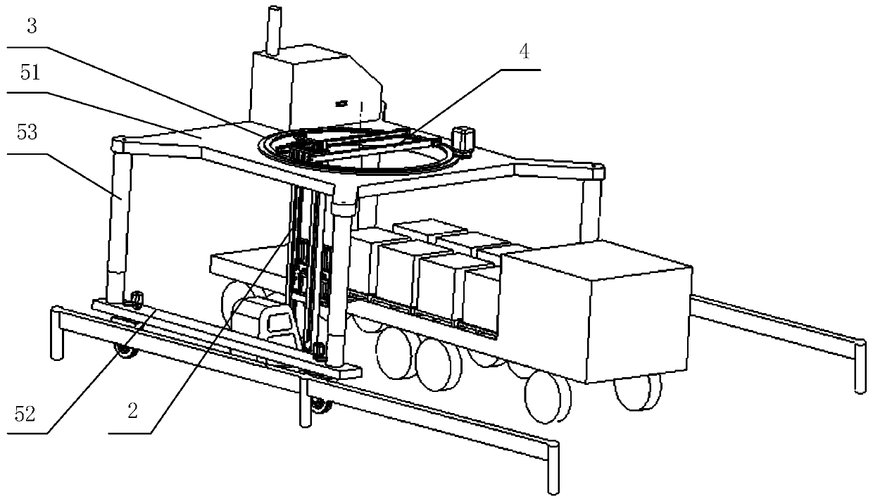
For example, when the forklift unloads the goods on one side of the truck, due to the limited telescopic length of the fork, the forklift needs to move to the other side of the truck to unload the goods, and the moving route of the forklift increases, resulting in slower unloading speed; When it is necessary to transfer the goods of one truck to another opposite truck in parallel, the forklift needs to turn around after supporting the goods, so that the goods can be transferred to another truck, and the turn will cause the forklift to transfer time becomes longer, and there is a risk that the forklift may not be able to turn smoothly because the moving aisle is too narrow
Another example is that forklifts cannot lower the forks to work below the ground, such as trenches, and forklifts cannot be used to lay tracks or disassemble pipes in trenches
Therefore, the actions that the existing forklifts can perform are relatively limited, the workplaces that can be adapted to are limited, and the adaptability is poor.

Method used


Image

  • Forklift
  • Forklift
  • Forklift

Examples


Embodiment Construction

[0058] The following will clearly and completely describe the technical solutions in the embodiments of the present invention with reference to the accompanying drawings in the embodiments of the present invention. Obviously, the described embodiments are only some, not all, embodiments of the present invention. Based on the embodiments of the present invention, all other embodiments obtained by persons of ordinary skill in the art without making creative efforts belong to the protection scope of the present invention.

[0059]In order to enable those skilled in the art to better understand the solution of the present invention, the present invention will be further described in detail below in conjunction with the accompanying drawings and specific embodiments.

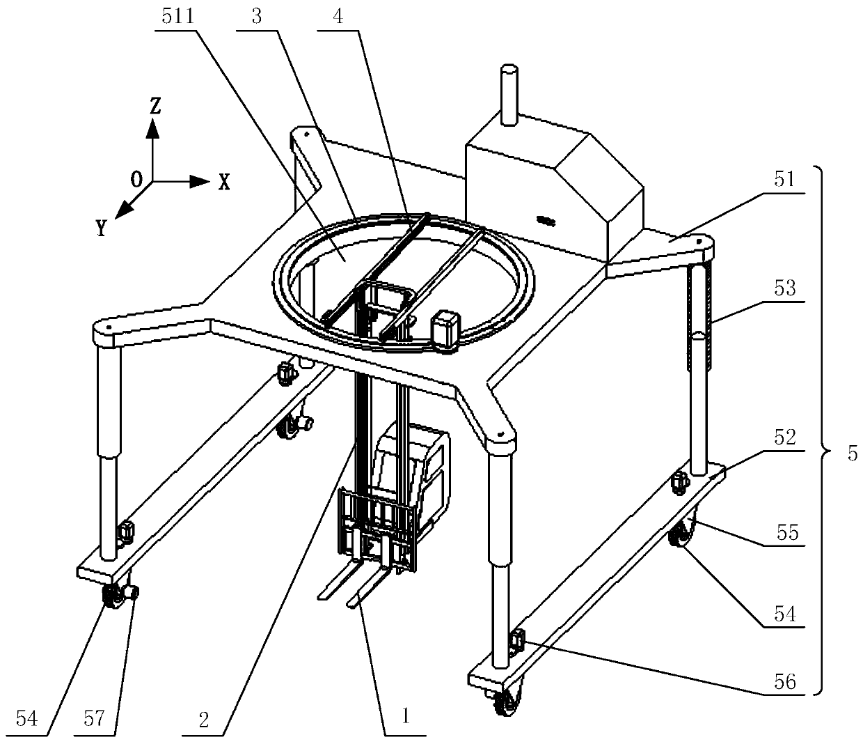
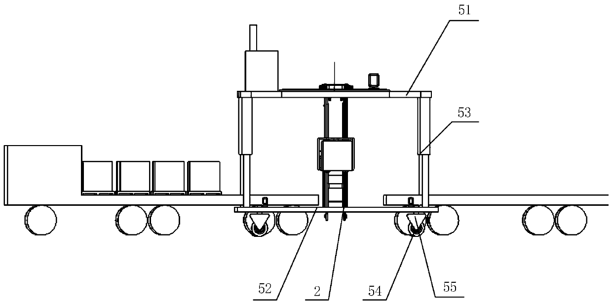
[0060] Please refer to Figure 1 to Figure 5 , figure 1 A structural diagram of a forklift provided for a specific embodiment of the present invention; figure 2 The state diagram of the forklift provided by the pr...


PUM


Abstract

The invention discloses a forklift. The forklift comprises a fork, a lifting device driving the fork to lift in the longitudinal direction, a rotating device driving the fork to rotate around the longitudinal axis, a horizontal moving device driving the fork to move horizontally along the horizontal plane to increase the retractable length of the fork and walking devices. The rotating device can make cargoes rotate without using the walking devices for steering, and the forklift can realize turning of cargo angles on the occasion that the walking devices cannot be steered due to too narrow space. When the cargoes on one side of a truck are unloaded, loading and unloading of the cargoes on the same side of the truck can be realized only by driving the fork to be close to the cargoes placedon the other side of the truck through the horizontal moving device; and when the cargoes of one truck need to be pulled in parallel to another truck placed relatively, what is only needed is to drivethe fork to move between the two trucks through the horizontal moving device. When the forklift needs to work in a trench lower than the ground, what is only needed is to make the lifting device drive the fork to descend to the ground under the support of the walking devices, the workplaces are increased, and the adaptability is good.

Description

technical field [0001] The invention relates to the field of forklifts, in particular to a forklift. Background technique [0002] Existing forklifts include wheels, frames, forks and masts, etc., which enable forklifts to carry heavy objects by lifting the forks. Rich and widely used in logistics, manufacturing, engineering and other fields, it is particularly necessary to optimize the performance of forklifts. [0003] During normal operation, the various parts of the forklift cooperate with each other to realize a series of actions such as lowering the fork, tilting the mast forward, moving the wheel forward, supporting the fork, tilting the mast backward, and lifting the fork. It is difficult to meet some special logistics requirements. For example, when the forklift unloads the goods on one side of the truck, due to the limited telescopic length of the fork, the forklift needs to move to the other side of the truck to unload the goods, and the moving route of the fork...

Claims


Application Information

Patent Timeline
Patent Type & Authority Applications(China)
IPC IPC(8): B66F9/14B66F9/24B66F9/075
CPCB66F9/149B66F9/24B66F9/0755B66F9/07572
Inventor 傅征王伟余鹏程汪俊豪周云凤
Owner HANGCHA GRP
Learn More