Manufacturing method of vehicle traction beam, vehicle traction beam and rail vehicle

A vehicle traction and manufacturing method technology, applied in the field of vehicle traction beams, can solve problems such as low machining accuracy and complicated manufacturing methods of traction beams, and achieve the effects of ensuring welding quality, reducing mold opening costs, and reducing the number of molds to be opened

Active Publication Date: 2019-11-22
CRRC QINGDAO SIFANG CO LTD
View PDF14 Cites 2 Cited by
  • Summary
  • Abstract
  • Description
  • Claims
  • Application Information

AI Technical Summary

Problems solved by technology

[0013] The purpose of the present invention is to provide a method for manufacturing a vehicle traction beam, a vehicle traction beam and a rail vehicle, so as to solve the problems of complex manufacturing methods and low machining accuracy of the traction beam in the prior art

Method used


Image

  • Manufacturing method of vehicle traction beam, vehicle traction beam and rail vehicle
  • Manufacturing method of vehicle traction beam, vehicle traction beam and rail vehicle
  • Manufacturing method of vehicle traction beam, vehicle traction beam and rail vehicle

Examples


Embodiment 1

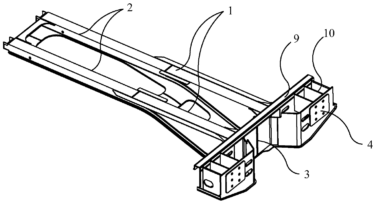
[0040] see in conjunction Figure 1 to Figure 8 , the manufacturing method of the vehicle traction beam includes the following steps: forming two traction beam webs 1 through a single profile; the traction beam web 1 and the lower cover plate 2 are spliced ​​to form a V-shaped groove and butt-welded to form the vehicle traction beam main body The main body of the vehicle traction beam is docked with the coupler mounting seat 3 to form a Y-shaped groove and welded; the curved surface mounting plate 5 is welded between the anti-climbing energy-absorbing device mounting seat 4 and the coupler mounting seat 3 .

[0041] The manufacturing method of the vehicle traction beam provided by the present invention and the vehicle traction beam form two traction beam webs 1 by using a single profile, so that the profile sections of the traction beam web 1 are unified, the number of molds is reduced, and the cost of mold opening is reduced. At the same time, the utilization rate of the prof...

Embodiment 2

[0059] According to another aspect of the present invention, the present invention provides a vehicle traction beam, including a lower cover plate 2, the vehicle traction beam is made by the manufacturing method of the vehicle traction beam in Embodiment 1; the outer edge of the lower cover plate 2 is provided with Traction beam patch 8. The overall structural strength of the lower cover plate 2 can be improved by providing the traction beam patch 8 , and further the overall structural strength of the vehicle traction beam can be further improved.

[0060] Further, the vehicle traction beam also includes a curved mounting plate 5 , and the two ends of the curved mounting plate 5 are respectively connected to the coupler mounting seat 3 and the anti-climbing energy-absorbing device mounting seat 4 .

[0061] The coupler mounting base 3 is fixedly connected to the traction beam. When the coupler mounting base 3 and the anti-climbing energy-absorbing device mounting base 4 are as...

Embodiment 3

[0063] According to another aspect of the present invention, the present invention provides a rail vehicle, including a buffer beam, a vehicle traction beam and a corbel, the buffer beam and the corbel are respectively connected to two ends of the vehicle traction beam, and the vehicle traction beam is the vehicle tow beam.

[0064] For other structures of the rail vehicle, reference may be made to the prior art, which will not be repeated herein. Since the vehicle traction beam has the above-mentioned technical effects, the rail vehicle including the vehicle traction beam also has corresponding technical effects, which will not be repeated here.


PUM

PropertyMeasurementUnit
surface smoothnessaaaaaaaaaa

Abstract

The invention provides a manufacturing method of a vehicle traction beam, the vehicle traction beam and a rail vehicle. The manufacturing method of the vehicle traction beam comprises the steps: forming two traction beam webs by using a single sectional material; splicing the traction beam webs and a lower cover plate to form a V-shaped groove, and carrying out butt welding to form a vehicle traction beam body; enabling the vehicle traction beam body to be in butt joint with a vehicle coupler mounting seat to form a Y-shaped groove, and then carrying out butt welding; and welding a curved surface mounting plate between an anti-climbing energy absorption device mounting seat and the vehicle coupler mounting seat. According to the manufacturing method of the vehicle traction beam and the vehicle traction beam, the single sectional material is used for forming the two traction beam webs, so that the machining efficiency is improved; the V-shaped groove is formed in the spliced position ofthe traction beam webs and the lower cover plate; the Y-shaped groove is formed in the spliced position of the vehicle traction beam and the vehicle coupler mounting seat, so that the welding operation difficulty is reduced, and the welding quality is ensured; and the curved surface mounting plate is welded to the position between the anti-climbing energy absorption device mounting seat and the vehicle coupler mounting seat, so that a long enough gap is reserved between a vehicle coupler and the vehicle coupler mounting seat.

Description

technical field [0001] The invention relates to the technical field of vehicle traction beams, in particular to a method for manufacturing a vehicle traction beam, a vehicle traction beam and a rail vehicle. Background technique [0002] There are many types of traction beam structures of aluminum alloy subway head cars in China. From the analysis of connection methods, overall structure of traction beams, welding methods and anti-climbing (energy absorption), etc., there are mainly deficiencies in the following aspects: [0003] 1. The connection method between the coupler mounting seat and the draw beam [0004] The hot riveting structure is adopted between the coupler mounting seat and the web of the traction beam. In this structure, the material of the coupler mounting seat is low-alloy steel. At the same time, the rivets are also low-alloy materials. Under the same volume, the mass is much greater than the aluminum profile; the structural weight is too large , unable t...

Claims


Application Information

Patent Timeline
Patent Type & Authority Applications(China)
IPC IPC(8): B23P15/00B23K31/02
CPCB23K31/02B23P15/00B23P2700/50
Inventor 刘志盛张成功田洪雷董晓李新康
Owner CRRC QINGDAO SIFANG CO LTD
Why Eureka
Try Eureka