Multi-lifting platform control system and method

A lifting platform and control system technology, applied in the field of lifting platforms, can solve the problems of wasting power resources, standby power consumption, low lifting frequency of lifting platforms, etc., and achieve the effects of saving power resources, avoiding insufficient voltage, and reducing costs

Inactive Publication Date: 2019-11-19
ZHEJIANG JIECHANG LINEAR MOTION TECH
View PDF16 Cites 1 Cited by
  • Summary
  • Abstract
  • Description
  • Claims
  • Application Information

AI Technical Summary

Problems solved by technology

Each lifting platform has a control module for controlling the lifting of the lifting platform. In the prior art, each lifting module is equipped with a power supply module for power supply, but the lifting frequency of the lifting platform is very low, that is, the frequency of use of the power supply module is very low. Moreover, after the power module is powered on, there is standby power consumption. In places where a large number of lifting platforms are used, a lot of power resources are wasted, which is not environmentally friendly and energy-saving, but also increases the manufacturing cost of the product, the purchase cost and the use cost of the customer.

Method used


Image

  • Multi-lifting platform control system and method
  • Multi-lifting platform control system and method
  • Multi-lifting platform control system and method

Examples


Embodiment 1

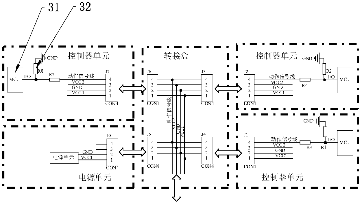
[0031] A control system for multiple lifting platforms, including a power supply module 1, an adapter module 2 and a plurality of control modules 3 that control the lifting of corresponding lifting platforms, the adapter module 2 is used to connect multiple control modules 3; the power supply module 1 and multiple control modules The modules 3 are connected to supply power to multiple control modules 3 at the same time; the control module 3 detects the operating status of other control modules 3 through the adapter module 2, and the control module 3 is set to detect that other control modules 3 are in the working state. The control module 3 is in a non-working state. The present invention realizes the connection between multiple control modules 3 through the adapter module 2, so that a single power supply module 1 can supply power to multiple control modules 3 at the same time, without requiring each control module 3 to be provided with a corresponding power supply module 1, re...

Embodiment 2

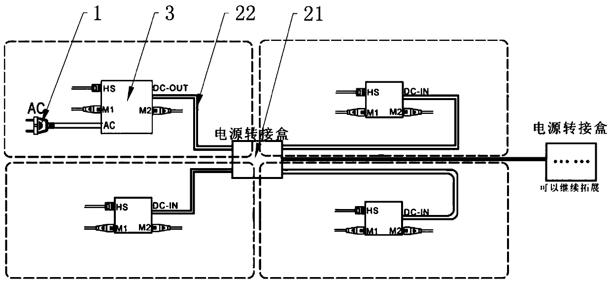
[0036] The difference between this embodiment and Embodiment 1 is that the control module 3 is a controller, and the power module 1 is a power supply unit installed in a certain controller. , the power supply unit can supply power to other controllers that are not provided with a power supply unit through the adapter box 21, and there is no need to provide a power adapter.

Embodiment 3

[0038] The difference between this embodiment and Embodiment 1 is that the adapter module 2 includes a plurality of adapter wires 22, the power module 1 is connected to one of the control modules 3, and the other control modules 3 are serially connected to the control module through the adapter wires 22 in turn. 3, the power supply module 1 realizes power supply to multiple control modules 3 through the adapter wire 22.


PUM


Abstract

The invention discloses a multi-lifting platform control system and method, and the system comprises a power module, a switching module and a plurality of control modules for controlling lifting of the corresponding lifting platforms, wherein the switching module is used for connecting the plurality of control modules; the power module is connected to the plurality of control modules for supplyingpower to the plurality of control modules at the same time; a control module detects the running state of the other control modules through the switching module, and the control module is not workingwhen being set to detect that the other control modules are in the working state. The multi-lifting platform control system and method provided by the invention realize the connection between the plurality of control modules through the switching module, so that a single power module can supply power to the plurality of control modules at the same time with no need to set a corresponding power module for each control module, thereby saving power resources and reducing the cost of the multi-lifting platform control system.

Description

technical field [0001] The invention belongs to the field of lifting platforms, and in particular relates to a control system and a control method for multiple lifting platforms. Background technique [0002] At present, lifting platforms are widely used in residential, office and medical fields, such as height-adjustable desks, cabinets, tatami mats, desks and medical beds, etc. Each lifting platform has a control module for controlling the lifting of the lifting platform. In the prior art, each lifting module is equipped with a power supply module for power supply, but the lifting frequency of the lifting platform is very low, that is, the frequency of use of the power supply module is very low. Moreover, after the power module is powered on, there is standby power consumption. In places where a large number of lifting platforms are used, a large amount of power resources are wasted, which is not environmentally friendly and energy-saving, while increasing product manufact...

Claims


Application Information

Patent Timeline
Patent Type & Authority Applications(China)
IPC IPC(8): G05B19/042
CPCG05B19/0423G05B2219/25257
Inventor 陆小健邓庆陈雪莉丁苗江
Owner ZHEJIANG JIECHANG LINEAR MOTION TECH
Why Eureka
Try Eureka