
An Improved Rotary Distribution Mechanism Based on Machining Device

A technology of material distributing mechanism and part seat, which is applied in the directions of packaging, loading/unloading, transportation and packaging, etc. It can solve the problems of unreasonable fixed structure of the feeding pipe, material falling into the ground, lack of material receiving mechanism, etc., and achieve improvement The rationality of the device structure and the effect of improving the functional structure

Active Publication Date: 2021-08-31
YANGZHOU HONGWEI MASCH EQUIP CO LTD
View PDF8 Cites 0 Cited by
  • Summary
  • Abstract
  • Description
  • Claims
  • Application Information

AI Technical Summary

Problems solved by technology

[0005] In order to solve the above-mentioned technical problems, the present invention provides an improved rotary material distribution mechanism based on a machining device to solve the existing rotary material distribution mechanism. When the pipe fittings with the pipe fitting structure are discharged downward, the material may be jammed. Therefore, it is necessary to disassemble the jammed pipe fittings and pound them downward during maintenance. The disassembled feeding pipe has no reasonable fixed structure. The downward direction of the discharge port is indeterminate, resulting in the material that is pounded out will fall into the ground, and there is a lack of reasonable material receiving mechanism.

Method used


Image

  • An Improved Rotary Distribution Mechanism Based on Machining Device
  • An Improved Rotary Distribution Mechanism Based on Machining Device
  • An Improved Rotary Distribution Mechanism Based on Machining Device

Examples


Embodiment

[0031] as attached figure 1 to attach Figure 8 Shown:

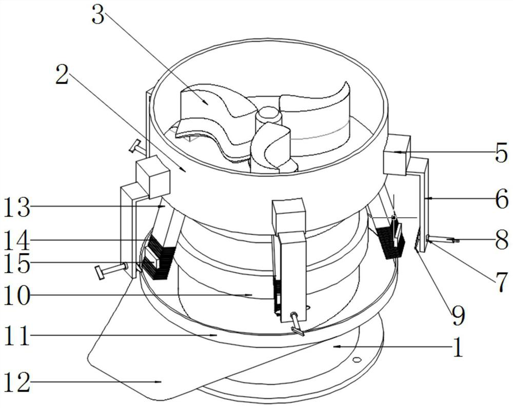
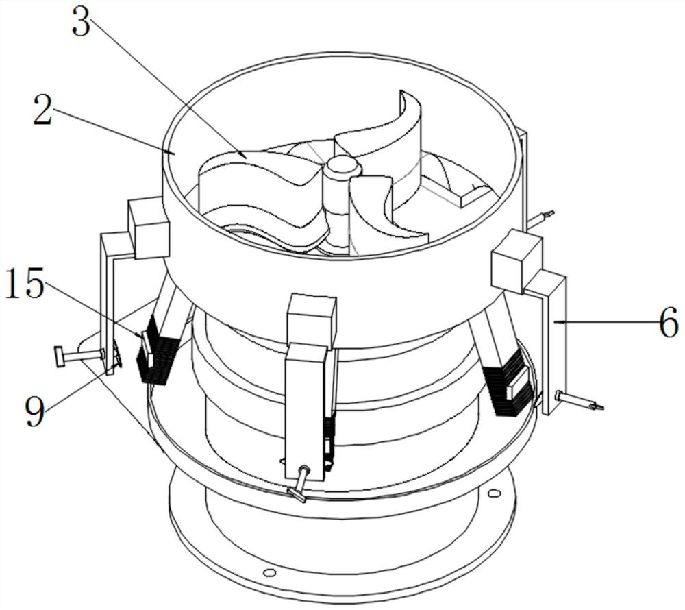
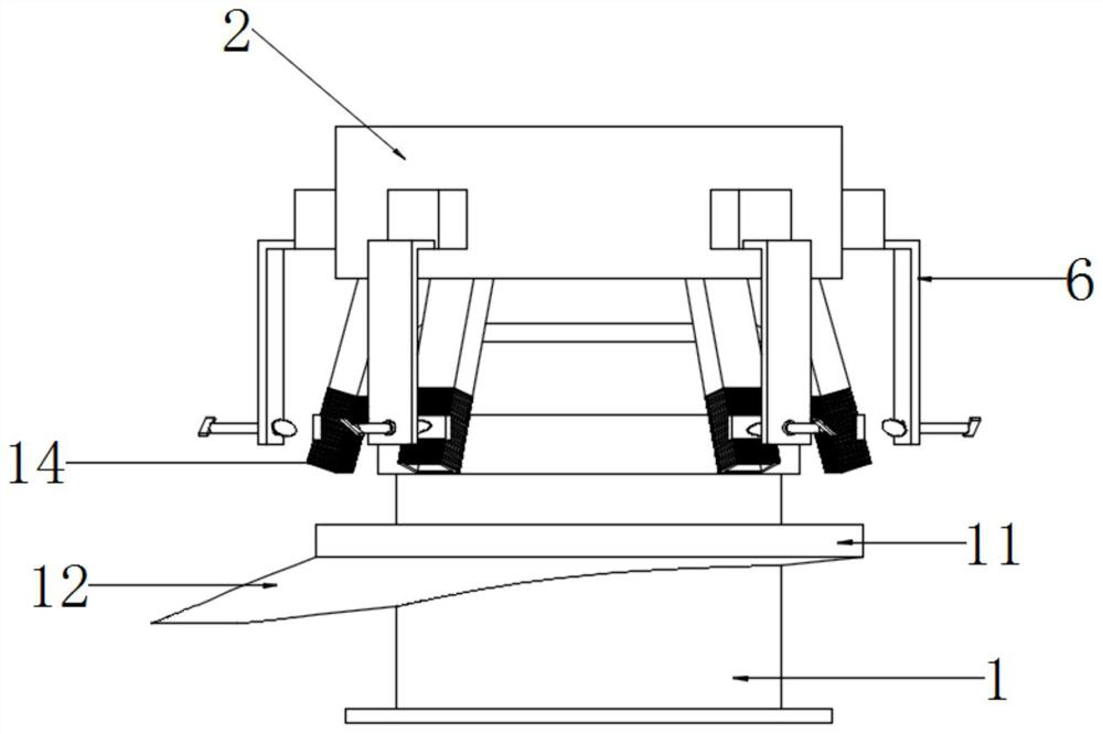
[0032] The invention provides an improved rotary material distribution mechanism based on a machining device, which includes a base 1, a distribution cabin 2, a distribution seat 3, a discharge port 4, a connecting seat 5, a turning plate 6, a threaded sleeve 7, and a push rod 8. Pressing plate 9, functional ring 10, connecting tank 11, orifice 12, feeding pipe 13, swing section 14 and pressure seat 15; the base 1 is a cylindrical cavity structure with a motor inside, and its top is seated There is a distributing cabin 2; the distributing cabin 2 is provided with three parts seats 3 which are fixedly connected to the motor shaft for rotating and agitating action, and a circle of square solid block structures is uniformly welded on the circular cavity wall of the distributing cabin 2 Connection seat 5; the bottom surface of the connection seat 5 is also welded with a turning plate 6 of L-shaped bent plate structure, and...


PUM


Abstract

The invention provides an improved rotary material distribution mechanism based on a machining device, which includes a swing section and a pressure seat; the base is a cylindrical cavity structure with a motor inside, and a dispensing cabin on the top; The distributing cabin is provided with three rotating and agitating dividing seats fixedly connected with the motor shaft, and a circle of connecting seats with a square solid block structure is evenly welded on the circular cavity wall of the distributing cabin; the bottom surfaces of the connecting seats are all There is also a turning plate with L-shaped bent plate structure welded. This device installs a temporary jacking structure on the outside of these discharge pipes, which can bend the disassembled bellows section inwards, so that the pipes that are pounded out from the pipe during maintenance The material naturally falls into the bottom-side tank. It can be seen from this that the multi-discharge pipe of the disc discharge structure has been greatly improved in terms of functional structure in the dimensional environment, and when the discharge pipe section is pressed down, It has a protective structure with reasonable inner and outer layers, which improves the rationality of the device structure.

Description

technical field [0001] The invention belongs to the technical field of distributing mechanism structure, and more specifically relates to an improved rotary material distributing mechanism based on a machining device. Background technique [0002] The distributing mechanism is nothing more than distributing the filled materials through a distributing device. The common one is a rotary distributing mechanism with a circular cabin structure. The material distribution plate or the material distribution seat makes the filled material rotate, and the material is distributed to the mouth of these discharge pipes during the material displacement process, so that the material is discharged downward along these discharge pipes to achieve the distribution of materials. Purpose. [0003] Based on the above, the designer found that the existing rotary distributing mechanism has a circle of feeding pipes at the bottom, and the pipe fittings of this type of multi-pipe distributing struct...

Claims


Application Information

Patent Timeline
Patent Type & Authority Patents(China)
IPC IPC(8): B65G65/40B65D88/64
CPCB65D88/64B65G65/40
Inventor 张婷
Owner YANGZHOU HONGWEI MASCH EQUIP CO LTD
Learn More