
Evaluation method of charging pile state

A charging pile and state technology, applied in charging stations, electric vehicle charging technology, electric vehicles, etc., can solve the problems of reduced performance, unfavorable charging pile maintenance, low efficiency, etc., to reduce the probability of failure and facilitate maintenance.

Active Publication Date: 2019-11-19
BEIJING SMARTCHIP MICROELECTRONICS TECH COMPANY +2
View PDF10 Cites 6 Cited by
  • Summary
  • Abstract
  • Description
  • Claims
  • Application Information

AI Technical Summary

Problems solved by technology

[0004] The faults of the charging pile mainly include the following types: the charging pile cannot continue charging due to accidental water ingress, foreign objects entering and leaving, and sudden changes in ambient temperature; during the charging process, the charger control device has a communication timeout, causing the charger to stop. The charging situation; during the charging process, the output voltage of the charger is greater than the total charging voltage of the vehicle; the aging of the charging pile or the long-term abnormal working state reduces its performance
[0005] Based on this, the inventors of the present application found that currently, for the faults and detection of the above-mentioned charging piles, they can only be repaired after the fault occurs, and a large amount of professional manpower and material resources are needed. Not only the operation and maintenance cost is high and the efficiency is low, but also cannot Carrying out state assessment based on the working condition data of the charging pile, it is impossible to judge the abnormal working state before the fault occurs, which is not conducive to the maintenance of the charging pile

Method used


Image

  • Evaluation method of charging pile state
  • Evaluation method of charging pile state
  • Evaluation method of charging pile state

Examples


Embodiment Construction

[0025] The specific embodiments of the present invention will be described in detail below in conjunction with the accompanying drawings, but it should be understood that the protection scope of the present invention is not limited by the specific embodiments.

[0026] Unless expressly stated otherwise, throughout the specification and claims, the term "comprise" or variations thereof such as "includes" or "includes" and the like will be understood to include the stated elements or constituents, and not Other elements or other components are not excluded.

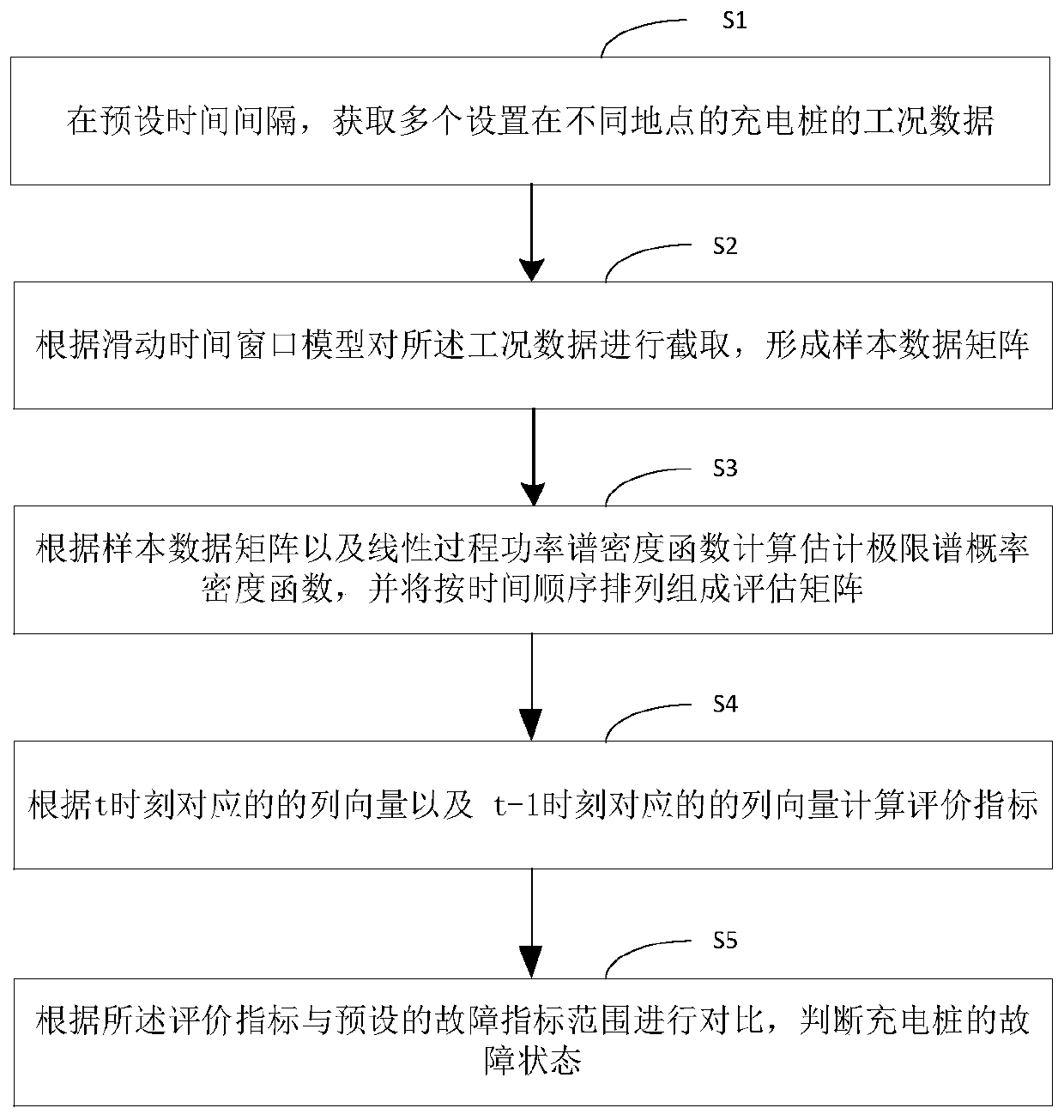
[0027] Such as figure 1 As shown, it is a flow chart of a method for evaluating charging pile status according to a preferred embodiment of the present invention, including steps S1-S5.

[0028] In step S1, at a preset time interval, the operating condition data of a plurality of charging piles arranged at different locations are acquired;

[0029] Wherein, the charging piles are set up in different locations, and the wor...


PUM


Abstract

The invention discloses an evaluation method of a charging pile state. The method comprises the steps that working condition data of a plurality of charging piles arranged at different places are acquired at a preset time interval; the working condition data are intercepted according to a sliding time window model to form a sample data matrix X caret t; an estimated limit spectrum probability density function h caret (x) is calculated according to the sample data matrix X caret t and a linear process power spectral density function, and h caret (x) is arranged according to the chronological order to form an evaluation matrix H caret (x); an evaluation index is calculated according to a column vector nt of H caret (x), corresponding to the moment t, and a column vector nt-1 of H caret (x),corresponding to the moment t-1; and according to the evaluation index, compared with a preset fault index range, the fault state of the charging piles is judged. According to the evaluation method ofthe charging pile state, the inner link between the working condition of the charging piles and various influence factors can be analyzed, the pre-judgment before a fault occurs is made, the fault probability of the charging piles is reduced, and the maintenance of the charging pile is facilitated.

Description

technical field [0001] The invention relates to a charging pile, in particular to a method for evaluating the state of a charging pile. Background technique [0002] With the increasing use of electric vehicles, the demand for charging piles is also increasing. Therefore, it is particularly important to detect the operating status of charging piles. [0003] At present, the detection of charging piles usually includes reporting the real-time working condition data of the charging pile, and the platform server collects the working condition data. If it is found that the charging pile does not report the working condition data at the preset time, or judge the equipment by other means Offline, the operation and maintenance management application will be notified of the abnormalities found, and then inspection instructions will be issued to professional maintenance personnel. Through manual surveys, the abnormalities found will be processed on-site, and the maintenance results ...

Claims


Application Information

Patent Timeline
IPC IPC(8): B60L53/60B60L53/68G06F17/16
CPCB60L53/60B60L53/68G06F17/16Y02T10/70Y02T10/7072Y02T90/12Y02T90/16
Inventor 师洋潘雨李涛王建
Owner BEIJING SMARTCHIP MICROELECTRONICS TECH COMPANY
Learn More