Feed chute and feed unit

A feeding device and feeding technology, applied in the field of feeding grooves, can solve problems such as large engineering complexity, and achieve the effects of long maintenance life and good elastic strength

Active Publication Date: 2022-06-07
MASCHINENFABRIK RIETER AG
View PDF9 Cites 0 Cited by
  • Summary
  • Abstract
  • Description
  • Claims
  • Application Information

AI Technical Summary

Problems solved by technology

Combined with a feed trough that can rotate about its axis, this implies considerable engineering complexity

Method used


Image

  • Feed chute and feed unit
  • Feed chute and feed unit
  • Feed chute and feed unit

Examples


Embodiment Construction

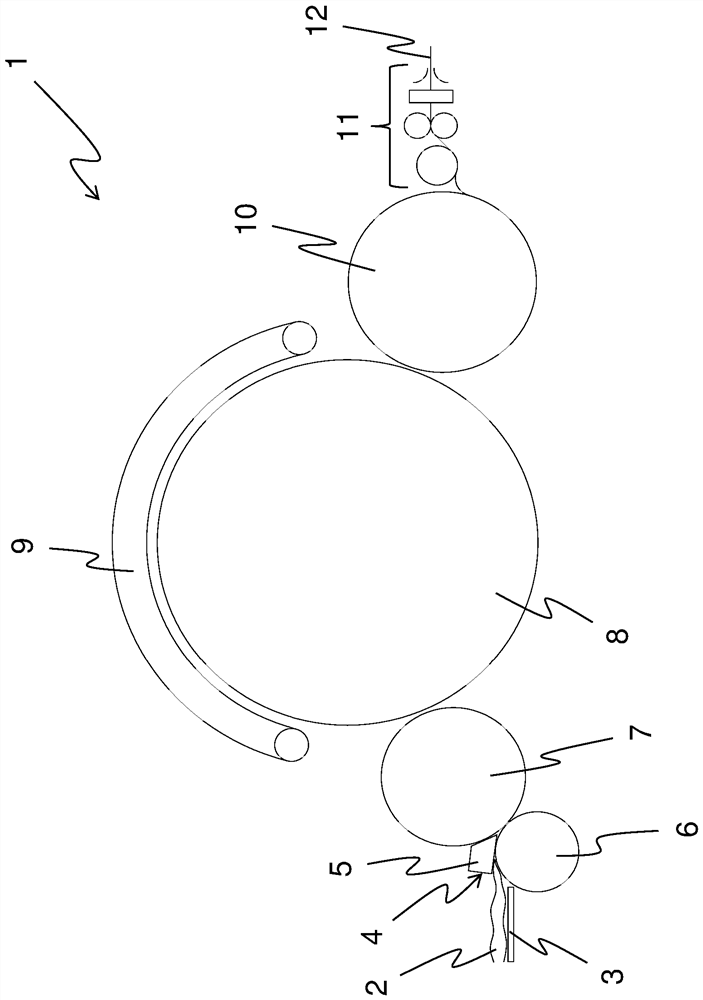
[0028] figure 1 A schematic side view of the carding machine 1 is shown. The fibers are conveyed in the carding machine 1 from left to right. The fibre mat 2 is first conveyed on the feeder plate 3 and then into the feeder 4 . The feeding device 4 has a feeding groove 5 which cooperates with a feeding roller 6 . The fiber mat 2 gripped between the feed slot 5 and the feed roller 6 is then fed to the feed roller 7 .

[0029] The nonwoven fibers proceed from the feed roller 7 to the cylinder 8 and are further processed between the cylinder 8 and the cover plate 9, which is shown here very schematically. The nonwoven fibers are then removed from the stripping roller 10 and conveyed to a compaction unit 11 where they are compacted into sliver 12 .

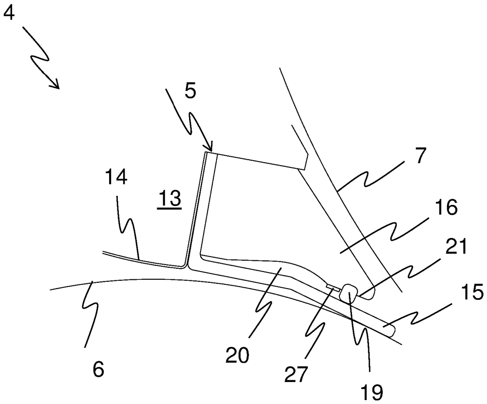
[0030] figure 2 A schematic side view of the feeding device 4 according to the invention is shown. The feeding means 4 can be as figure 1 Part of a card 1 is shown, but it could also be part of a card or a cleaner. The feeding...


PUM

PropertyMeasurementUnit
thicknessaaaaaaaaaa

Abstract

The invention relates to a feed chute (5) for a feed device (4) for feeding fiber bundles into a spinning preparation machine, said feed chute comprising a body (13) and at least one elastic lip ( 15), the elastic lip extends over the working width of the feed slot (5). According to the invention, a support strip (16) is arranged on said base body (13), said support strip extending along said working width, said support strip (16) being at a distance from said elastic lip (15) , said distance being such that said distance can be eliminated by elastic deformation of said elastic lip (15). The invention also relates to a feed device (4) for feeding fiber bundles into a spinning preparation machine, said feed device comprising a feed roller (6) and a feed chute (5) according to the preceding description.

Description

technical field [0001] The invention relates to a feed slot for feeding fibre bundles to a feeding device in a spinning preparation machine, the feed slot comprising a base body and at least one elastic lip extending along the working width of the feed slot, And the invention relates to a feeding device for feeding a fiber bundle into a spinning preparation machine, comprising a feeding roller and a feeding slot. Background technique [0002] Feed troughs for feeding devices are known from EP 0 926 274 A2. The feed slot has an elastically deformable element formed by a gap, which element is fastened to the support element. Preferably, at least larger foreign bodies do not penetrate into this elastic region. Such foreign matter has been captured upstream from the elastic edge region between the gap-forming element and the feed roller. The feed slot then rotates about the axis as a whole against the bias of the spring. This fact is detected by sensors, in which foreign obj...

Claims


Application Information

Patent Timeline
Patent Type & Authority Patents(China)
IPC IPC(8): D01G9/16D01G15/20
CPCD01G9/16D01G15/40D01G31/003D01G15/20
Inventor P.杰里耐克C.穆勒
Owner MASCHINENFABRIK RIETER AG
Why Eureka
Try Eureka