Method for fastening a rail of an elevator system in an elevator shaft

A technology for elevator shafts and guide rails, which is applied in the direction of mechanical equipment, fixed rails, and friction-clamped detachable fasteners. It can solve problems such as loss of function of elastic materials, overload of elastic materials, and application of screws to achieve length compensation. performance, reliable clamping force, and the effect of reducing the range of variation

Active Publication Date: 2019-11-15
INVENTIO AG
View PDF7 Cites 0 Cited by
  • Summary
  • Abstract
  • Description
  • Claims
  • Application Information

AI Technical Summary

Problems solved by technology

In addition, elastic materials may lose their functionality due to component aging
In addition, there is a problem when installing that the tightening force of the screws must be applied very quantitatively and there is a risk of overloading the elastic material in case of accidental tightening

Method used


Image

  • Method for fastening a rail of an elevator system in an elevator shaft
  • Method for fastening a rail of an elevator system in an elevator shaft
  • Method for fastening a rail of an elevator system in an elevator shaft

Examples


Embodiment Construction

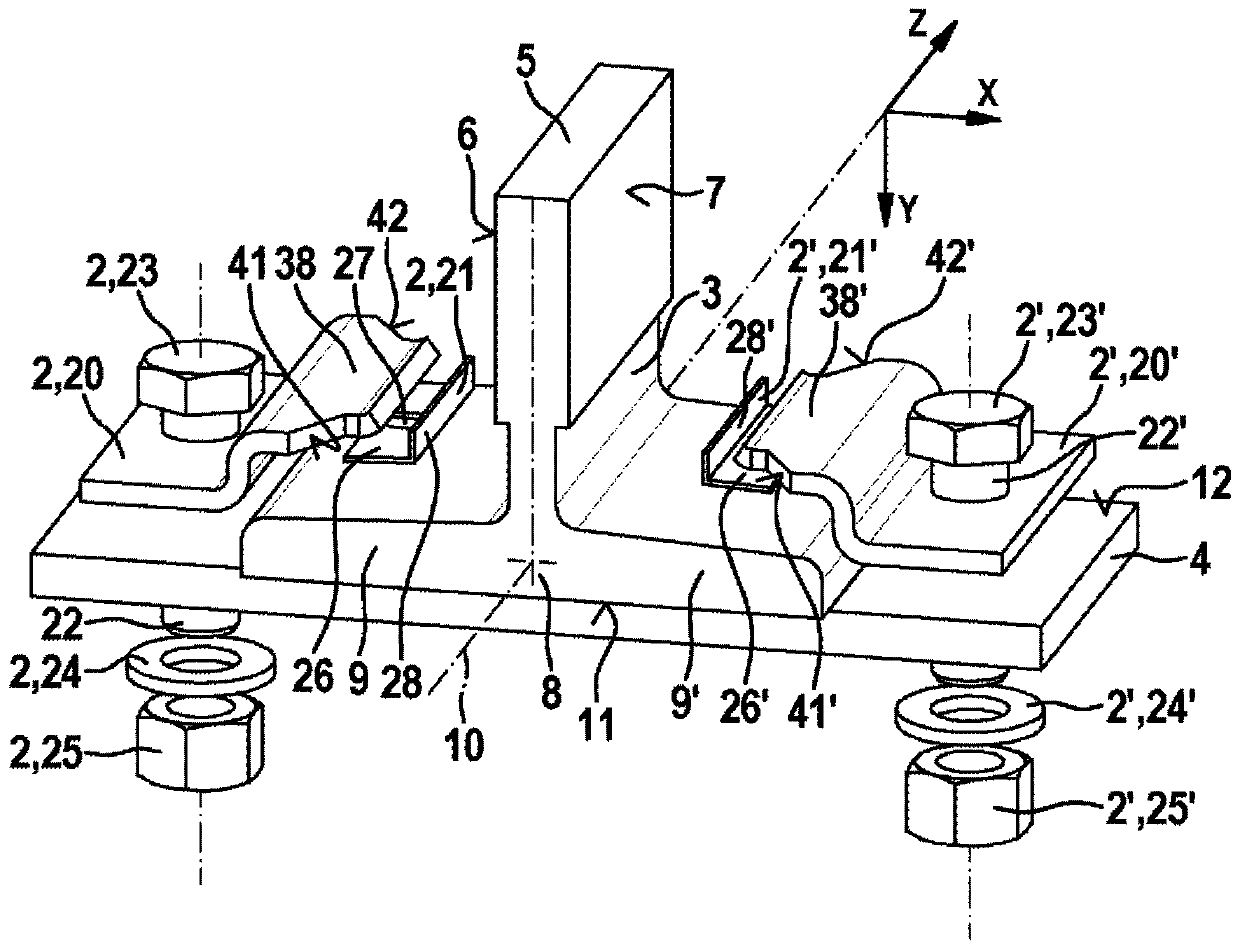
[0039] figure 1 shows the elevator installation 1 ( Figure 4 ) of the guide rail 3, which is fixed on the support body 4 by the clamping set 2 and the clamping set 2', for explaining the first embodiment. The guide rail 3 has a guide rail head 5 with guide surfaces 6 , 7 . Furthermore, the guide rail 3 has a guide rail foot 8 with sides 9, 9'. as well Figure 4 As shown, the guide rail 3 extends along its extension 10 through the elevator shaft 11 when the guide rail 3 is installed. For the sake of explanation, a direction Z is defined here along the extension 10 . The underside 11 of the rail foot 8 is placed on the upper side 12 of the carrier 4 during installation. In this case, the degree of freedom in the direction Y is limited by the upper side 12 . With respect to the right-handed coordinate system, there is also a direction X.

[0040] In the fixed state, the guide rail 3 should be displaceable relative to the support body 4 in and against the direction Z in or...


PUM


Abstract

The invention relates to a method for fastening a rail (3) of an elevator system (1) to at least one bearing element (4), which is fixed in an elevator shaft (16), by means of at least one clamp set (2) which has a clamp (20) and a spacer (21). In the method, the clamp (20) is arranged on a side part (9) of a rail foot (8) of the rail (3), said side part being arranged on the bearing element (4),such that the clamp (20) can be connected to the bearing element (4) in a fastening zone (34) of the clamp (20) and that a contact zone (30) of the clamp (20) is situated on a bearing side (36) on anupper face (37) of the side part (9) of the rail foot (8). The spacer (21) defines a mounting distance ([delta]d) between the contact zone (30) of the clamp (20) and the bearing side (36) on the upperface (37) of the side part (9) of the rail foot (8) such that the clamp (20) is partly elastically and partly plastically deformed in the fastening zone (34) thereof, when the clamp (20) is connectedto the bearing element (4). The spacer (21) is then at least partially removed so that a distance (68) between the contact zone (30) of the clamp (20) and the bearing side (36) on the upper face (37)of the side part (9) of the rail foot (8) is reduced. The invention also relates to an elevator system (1) which has at least one rail (3) which is mounted using such a method. The invention furtherrelates to a clamp set (2) for fastening a rail (3) of an elevator system (1) to at least one bearing element (4) which is fixed in an elevator shaft (16).

Description

technical field [0001] The invention relates to a method for fastening guide rails of an elevator installation in an elevator shaft, a clamping set for fastening guide rails of an elevator installation in an elevator shaft, and an elevator installation installed in an elevator shaft. Background technique [0002] A rail foot holder is known from ES 2 421 083 A1, in which in the assembled state lateral parts of the main body press against the upper side of the side parts of the rail foot. Here, the lateral portion is arranged on one side of the fixed axis for the main body, while on the other side of the fixed axis there is an elastic material supporting the main body. The screw is tightened along the fixing axis, wherein the screw head presses against the body, which on the one hand exerts a compressive force on the lateral part to hold the rail foot and on the other hand keeps the body in contact with the elastic material. If the lateral part of the main body is now lifted...

Claims


Application Information

Patent Timeline
Patent Type & Authority Applications(China)
IPC IPC(8): B66B7/02
CPCB66B7/024E01B9/66F16B2/12
Inventor 埃曼努尔·费里托尔斯滕·索内尔彼得·默里
Owner INVENTIO AG
Why Eureka
Try Eureka