
Intelligent control system of air source heat pump

A technology of air source heat pump and control system, applied in heating and ventilation control system, space heating and ventilation, heating and ventilation safety system, etc. Problems such as poor experience can reduce the maintenance time of after-sales personnel and customers, facilitate viewing and control of terminal equipment, and ensure long-term operation

Inactive Publication Date: 2019-11-15
WUHAN COMFORTABLE YIBAI TECH
View PDF4 Cites 1 Cited by
  • Summary
  • Abstract
  • Description
  • Claims
  • Application Information

AI Technical Summary

Problems solved by technology

[0002] The current air source heat pump equipment field adopts the traditional production and sales model. After the production is completed, sales will be carried out by the sales channel. After installation and use, the user has been in a passive service mode. After the abnormality, you need to contact the after-sales service to understand the specific problem. After the after-sales service receives the warranty or consultation complaint, it needs to judge the user's problem based on experience. Whether it is necessary to replace accessories and many other issues; this maintenance method is passive; on the one hand, it will have a great impact on the cost of after-sales service because of the need for local after-sales service; on the other hand, the user experience is relatively poor; Damaged, when parts need to be replaced, it will waste a lot of time and cost of replacement parts for customers
[0003] The vast majority of equipment failures are mainly caused by users not paying attention to equipment maintenance during daily use; therefore, an intelligent solution is urgently needed to allow after-sales parties and users to grasp the operation status of equipment in real time, and reduce after-sales and maintenance costs. The time cost and equipment accessories cost incurred by both users due to equipment failure

Method used


Image

  • Intelligent control system of air source heat pump

Examples


Embodiment Construction

[0035] The following will clearly and completely describe the technical solutions in the embodiments of the present invention with reference to the drawings in the embodiments of the present invention.

[0036] It should be noted that, in the description of the present invention, it should be noted that, for example, the terms "center", "upper", "lower", "left", "right", "vertical", "horizontal", " The orientation or positional relationship indicated by "inner", "outer", etc. is based on the orientation or positional relationship shown in the drawings, which is only for the convenience of describing the present invention and simplifying the description, rather than indicating or implying that the referred device or element must have a specific orientation, are constructed and operate in a particular orientation and therefore are not to be construed as limiting the invention.

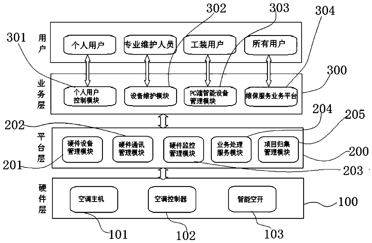
[0037] combine figure 1 It can be seen that the air source heat pump intelligent control system incl...


PUM


Abstract

The invention discloses an intelligent control system of an air source heat pump. The system comprises a hardware layer, a platform layer and a business layer, the hardware layer comprises multiple terminal devices which are electrically connected, the platform layer is used for processing collected data information fed back by the hardware layer and feeding the information back to the business layer, the information fed back by the business layer is processed and then transmitted to the hardware layer, the business layer is used for providing managing for different types of customers, configuring and maintaining operation platforms of the terminal devices of the hardware layer and providing early warning information to be fed back to the different types of users, the control system can monitor running conditions of multiple terminal devices of the hardware layer in real time through modules of the platform layer and the business layer, early warning information and a solution are provided, manpower and material sources are greatly saved, the after-sales service efficiency is improved, the after-sales cost is reduced, and the user experience effect is improved.

Description

technical field [0001] The invention relates to an air source heat pump control system, in particular to an air source heat pump intelligent control system, which belongs to the technical field of air source heat pumps. Background technique [0002] The current air source heat pump equipment field adopts the traditional production and sales model. After the production is completed, sales will be carried out by the sales channel. After installation and use, the user has been in a passive service mode. After the abnormality, you need to contact the after-sales service to understand the specific problem. After the after-sales service receives the warranty or consultation complaint, it needs to judge the user's problem based on experience. Whether it is necessary to replace accessories and many other issues; this maintenance method is passive; on the one hand, it will have a great impact on the cost of after-sales service because of the need for local after-sales service; on the...

Claims


Application Information

Patent Timeline
Patent Type & Authority Applications(China)
IPC IPC(8): F24F11/58F24F11/47F24F11/38F24F11/63
CPCF24F11/38F24F11/47F24F11/58F24F11/63
Inventor 韩英春余轶刘雪浩
Owner WUHAN COMFORTABLE YIBAI TECH
Learn More