
Numerical control square lathe

A square machine and turning machine technology, applied in the field of CNC turning machines, can solve the problems of affecting the machining surface accuracy, increase labor, and low processing efficiency, and achieve the effects of improving machine tool accuracy, high transmission accuracy, and easy chip removal.

Inactive Publication Date: 2019-11-15
广州和兴机电科技有限公司
View PDF6 Cites 2 Cited by
  • Summary
  • Abstract
  • Description
  • Claims
  • Application Information

AI Technical Summary

Problems solved by technology

[0002] The traditional machining concept of CNC lathes is that they can only process circular rotary parts, not plane or flat parts. To process planes, they must be processed on a CNC milling machine. For example, in many shaft parts, circular shafts need to be processed. For the shaft body of square or regular polygon, milling is usually used for milling. The processing efficiency is low, which not only increases the labor but also cannot avoid the accuracy error caused by the secondary clamping.
In addition, the current machine tools of the turning side are relatively single, and can only process fixed polygons, and cannot realize controlled machining of arbitrary polygons. Due to the limitation of the mechanical structure, the rigidity of the machine tool during turning side machining will be insufficient, which will affect the machining surface accuracy.

Method used


Image

  • Numerical control square lathe
  • Numerical control square lathe

Examples


Embodiment Construction

[0019] The technical solutions of the present invention will be further described below in conjunction with the accompanying drawings and through specific implementation methods.

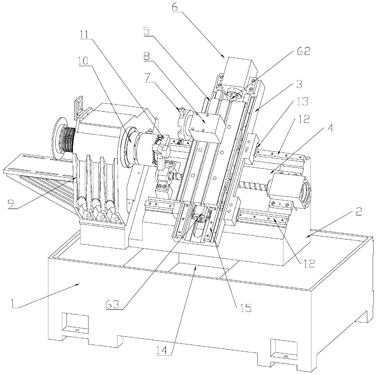
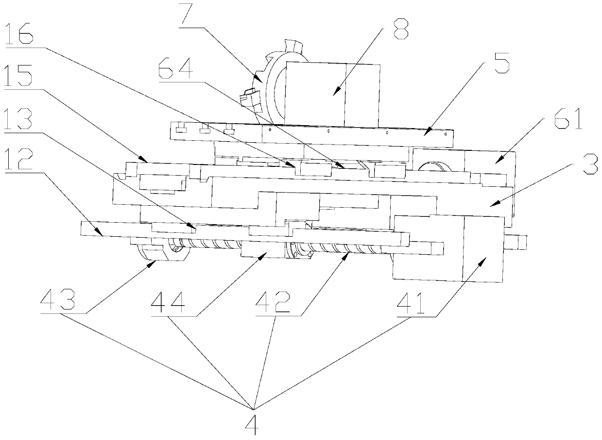
[0020] Such as figure 1 as well as figure 2 As shown, it is an embodiment of a CNC turning machine of the present invention, including a bed 1, a fixed seat 2, a movable seat 3, a first moving mechanism 4 that can make the movable seat 3 horizontally reciprocate left and right, a fixed frame 5, a second Two moving mechanism 6, flying cutter head 7 and the car side power head 8 that provides power for flying cutter head 7 to rotate, fixed seat 2, moving seat 3, first moving mechanism 4, fixed mount 5, second moving mechanism 6, flying The cutter head 7 and the turning power head 8 are all located above the bed 1; the fixed seat 2 is arranged in a right-angled trapezoidal shape and fixed on the top of the bed 1, and the first moving mechanism 4 is embedded in the inclined surface of the fixed seat 2...


PUM


Abstract

The invention discloses a numerical control square lathe and relates to the technical field of mechanical processing equipment. The numerical control square lathe comprises a lathe body, a fixed seat,a movable seat, a first movable mechanism, a fixed frame, a second movable mechanism, a fly cutter disc and a square power head, wherein the fixed seat is arranged in a right-angle trapezoid shape and is fixed on the top of the lathe body; the first movable mechanism is embedded in the inclined surface of the fixed seat; the fly cutter disc is fixed at the power output end of the square power head; the second movable mechanism is embedded in the upper surface of the movable seat so that the fixed frame can reciprocate vertically along the upper surface of the movable seat; the fly cutter disc, the square power head and the first movable mechanism are all parallel to the inclined surface; the left end of the fixed seat is also fixed with a connecting frame, a driving motor is fixed on theconnecting frame, and a chuck is fixed at the power output end of the driving motor. The lathe can turn a workpiece into any shape, is multifunctional and has high square surface accuracy.

Description

technical field [0001] The invention relates to the technical field of mechanical processing equipment, in particular to a numerically controlled square turning machine. Background technique [0002] The traditional machining concept of CNC lathes is that they can only process circular rotary parts, not plane or flat parts. To process planes, they must be processed on a CNC milling machine. For example, in many shaft parts, circular shafts need to be processed. The shaft body that is square or regular polygon is usually milled by milling machine, the processing efficiency is low, which not only increases the labor but also cannot avoid the accuracy error caused by the secondary clamping. In addition, the function of the current lathe machine tool is relatively single, and can only process fixed polygons, and cannot realize controlled machining of arbitrary polygons. Due to the limitation of the mechanical structure, the rigidity of the machine tool during lathe processing wi...

Claims


Application Information

Patent Timeline
IPC IPC(8): B23B5/24
CPCB23Q27/00
Inventor 刘应省宋小平曹志文
Owner 广州和兴机电科技有限公司
Learn More