Function switching method and device, computer device and computer readable storage medium
A technology of function switching and intelligent equipment, applied in computing, multi-program device, program startup/switching, etc., can solve problems such as cumbersome operation and rigid function selection scheme, and achieve the effect of achieving a degree of storage and shortening the development cycle
- Summary
- Abstract
- Description
- Claims
- Application Information
AI Technical Summary
Problems solved by technology
Method used
Image

Examples
Embodiment 1
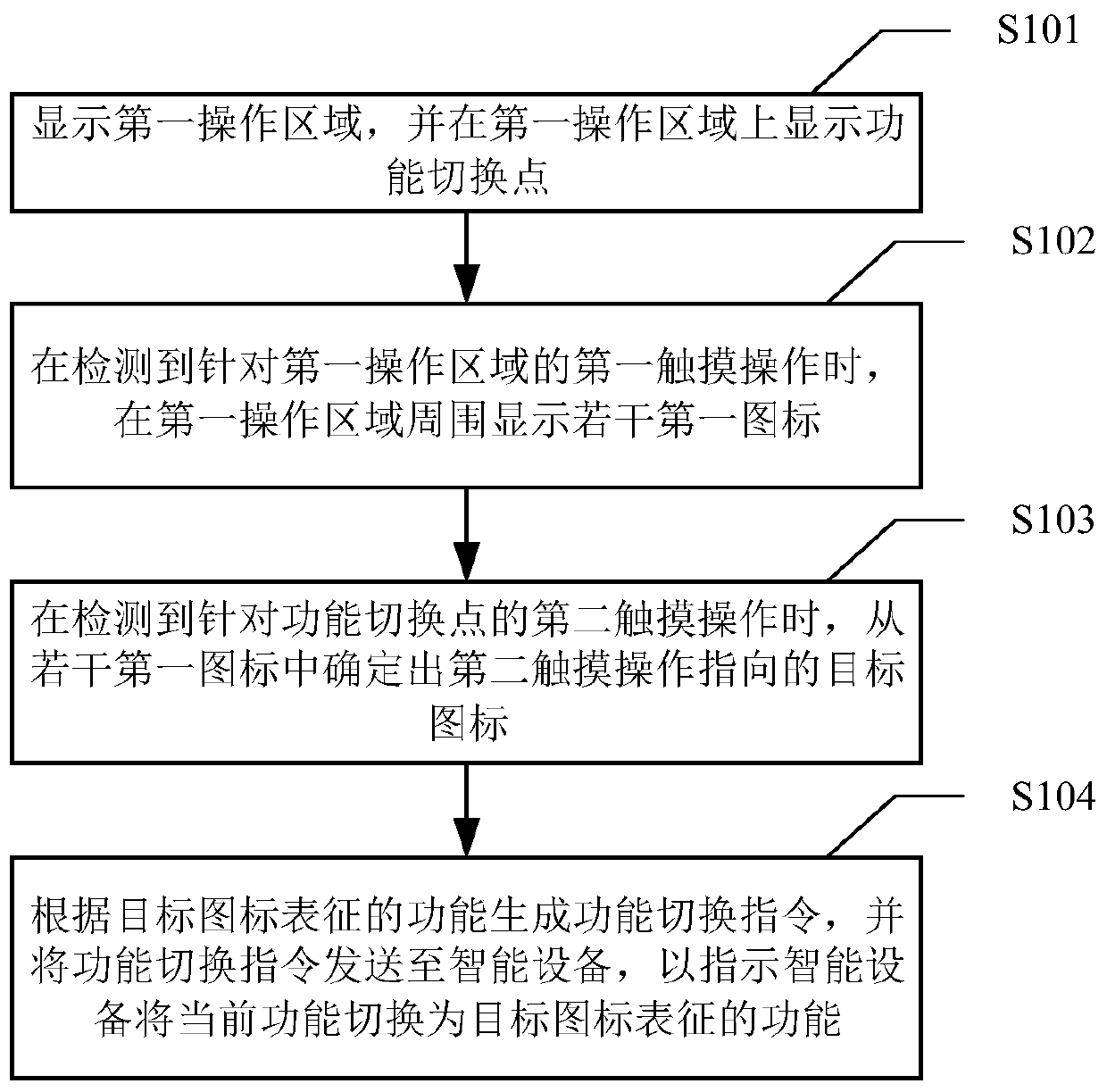
[0034]Embodiment 1 of the present invention provides a function switching method, which can be applied to the following business scenarios: the function switching method can be applied to the client, the client can control multiple smart devices, and when a smart device needs to be switched When using the function of the smart device, you can enter the device control page of the smart device, and then execute the function switching method provided by the present invention on the device control page to quickly switch the function of the smart device, improve the flexibility of function selection, and reduce the cumbersomeness of operation. specifically, figure 1 A flow chart of the function switching method provided by Embodiment 1 of the present invention, such as figure 1 As shown, the function switching method may include steps S101 to S104, wherein:
[0035] Step S101, displaying a first operation area, and displaying a function switching point on the first operation area....
Embodiment 2
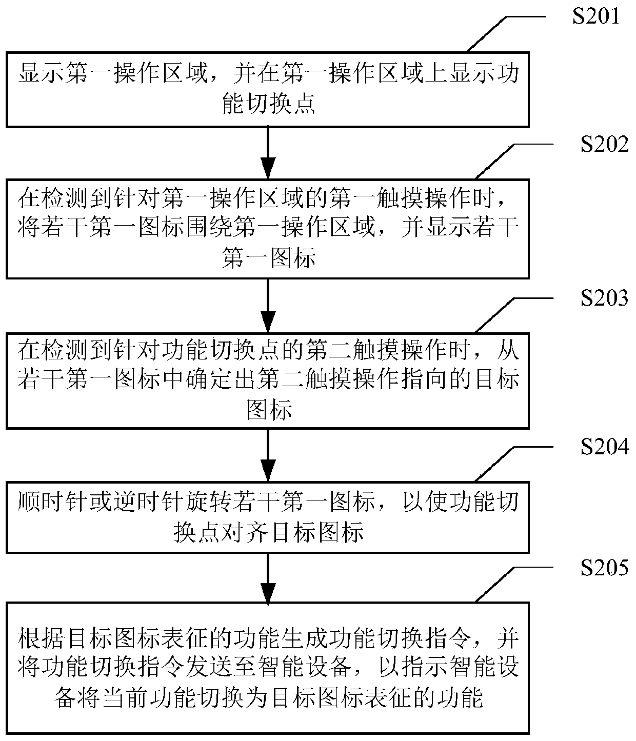
[0047] Embodiment 2 of the present invention provides a function switching method. Part of the steps of the function switching method are corresponding to the steps in the above-mentioned embodiment 1. These steps will not be repeated in this embodiment. For details, please refer to the above-mentioned embodiment. one. specifically, figure 2 A flow chart of the function switching method provided by Embodiment 2 of the present invention, such as figure 2 As shown, the function switching method may include steps S201 to S205, wherein:
[0048] Step S201, displaying a first operation area, and displaying a function switching point on the first operation area.
[0049] Step S202, when a first touch operation on the first operation area is detected, surrounding the first operation area with several first icons and displaying the several first icons.
[0050] In this embodiment, several first icons are displayed around the first operating area. For example, if the first operat...
Embodiment 3
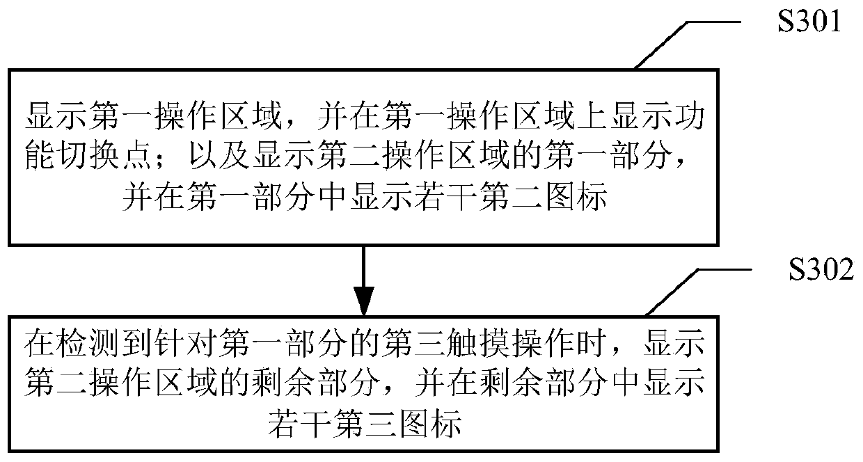
[0058] Embodiment 3 of the present invention provides a function switching method. Some steps of the function switching method are corresponding to the steps in the above-mentioned embodiment 1. These steps will not be repeated in this embodiment. For details, please refer to the above-mentioned embodiment one. specifically, image 3 A flow chart of the function switching method provided by Embodiment 3 of the present invention, such as image 3 As shown, the function switching method may include steps S301 to S302, wherein:
[0059] Step S301, displaying the first operation area, and displaying the function switching point on the first operation area; and displaying the first part of the second operation area, and displaying several second icons in the first part.
[0060] In this embodiment, the device control page may further include a second operation area. When entering the device control page, the first operation area and the first part of the second operation area may...
PUM
 Abstract
Description
Claims
Application Information
 - R&D
- Intellectual Property
- Life Sciences
- Materials
- Tech Scout
- Unparalleled Data Quality
- Higher Quality Content
- 60% Fewer Hallucinations
Browse by: Latest US Patents, China's latest patents, Technical Efficacy Thesaurus, Application Domain, Technology Topic, Popular Technical Reports.
© 2025 PatSnap. All rights reserved.Legal|Privacy policy|Modern Slavery Act Transparency Statement|Sitemap|About US| Contact US: help@patsnap.com