Plane thrust ball bearing automatic ball injection riveting machine

A thrust ball bearing and riveting machine technology, applied in the field of thrust ball bearings, can solve problems such as low work efficiency, worker fatigue, and consumption, and achieve the effects of improving production efficiency, ensuring product quality, and reducing costs

Active Publication Date: 2019-11-12
新昌县精艺轴承有限公司
View PDF8 Cites 2 Cited by
  • Summary
  • Abstract
  • Description
  • Claims
  • Application Information

AI Technical Summary

Problems solved by technology

[0004] In view of the above situation, in order to overcome the defects of the prior art, the present invention provides an automatic ball injection riveting machine for plane thrust ball bearings, which effectively solves the problem of consuming a lot of manpower and material resources, low work efficiency, and Issues that affect product quality due to worker fatigue, proficiency, etc.

Method used


Image

  • Plane thrust ball bearing automatic ball injection riveting machine
  • Plane thrust ball bearing automatic ball injection riveting machine
  • Plane thrust ball bearing automatic ball injection riveting machine

Examples


Embodiment 1

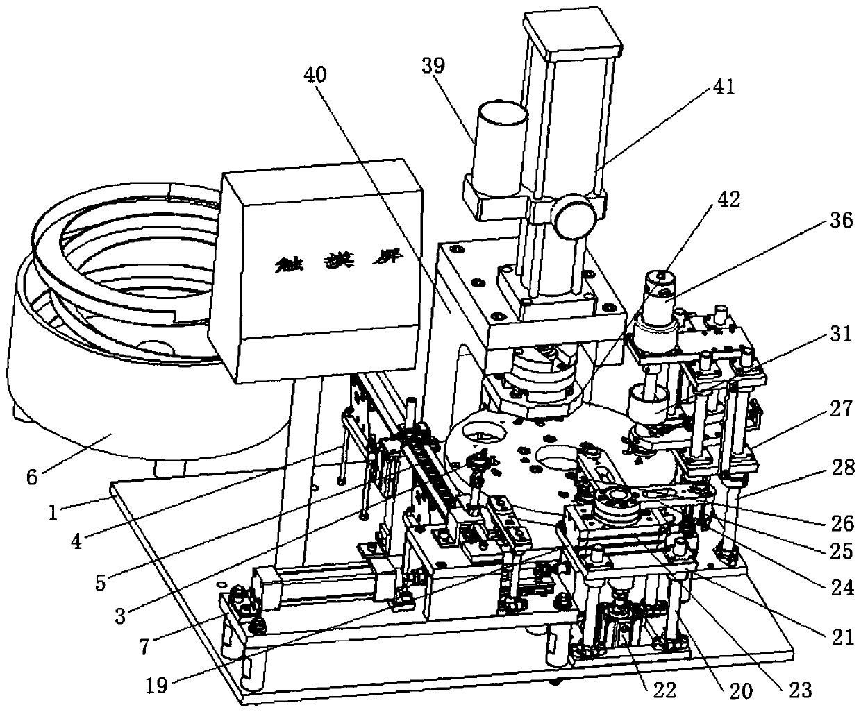
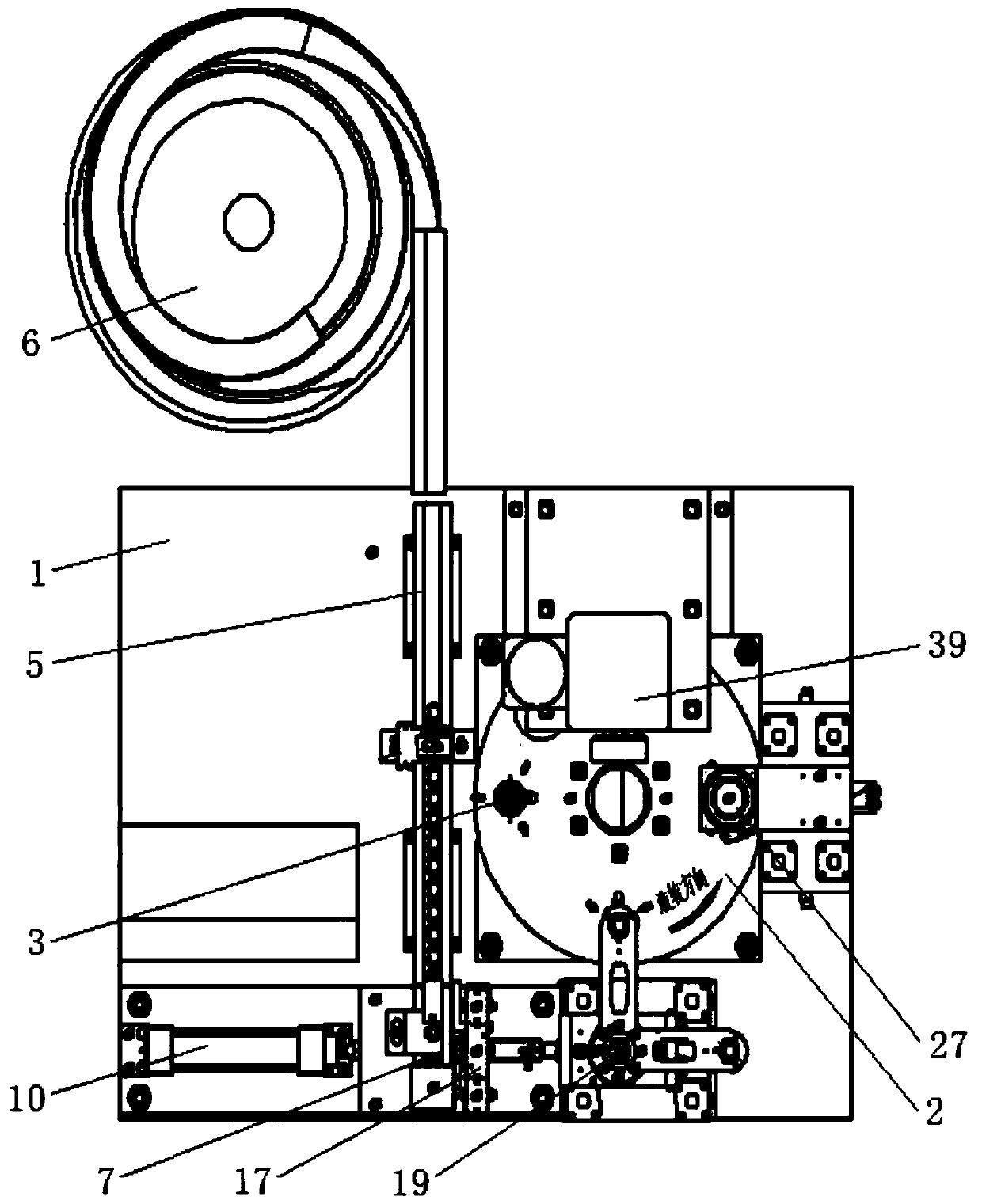
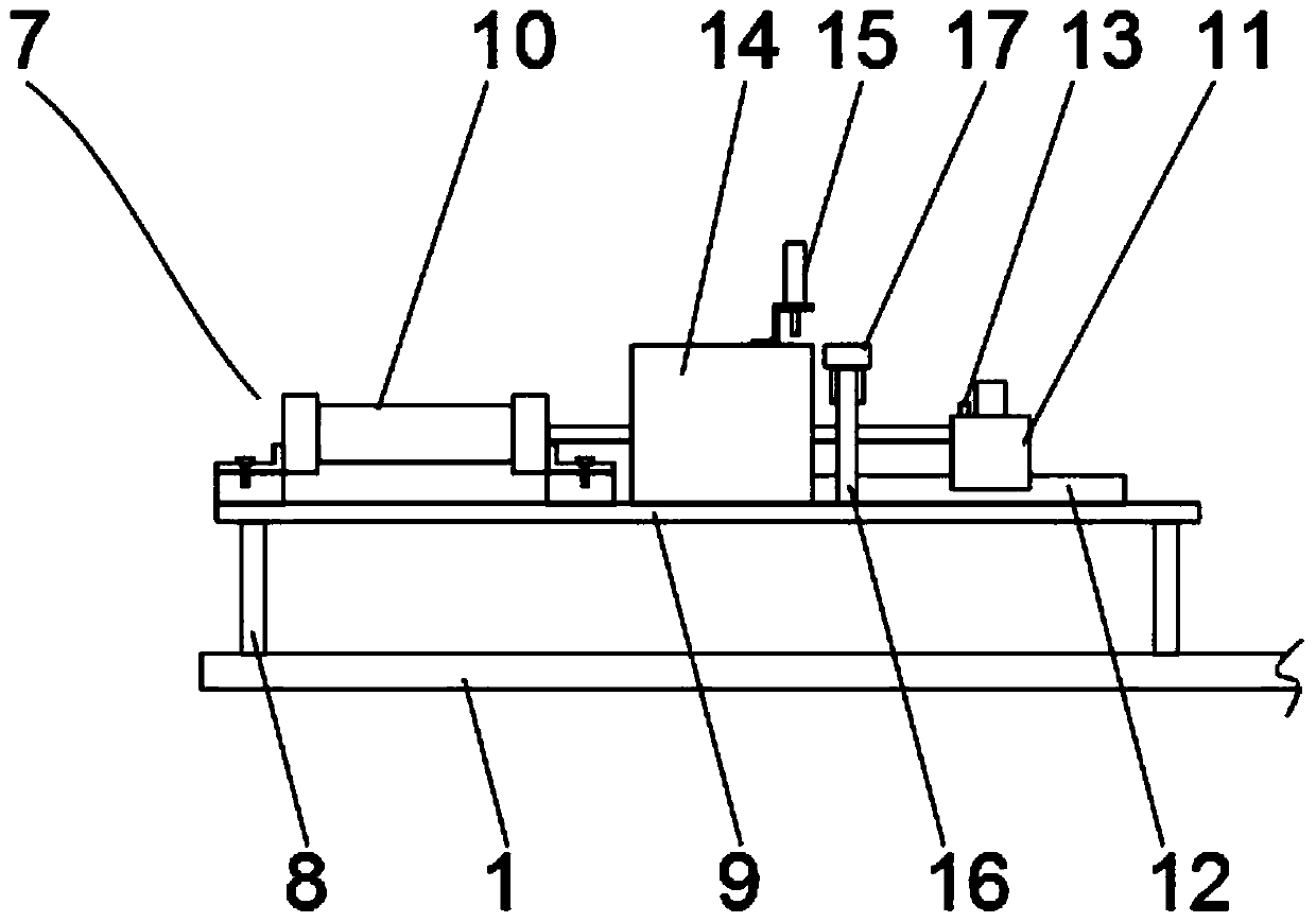
[0032] Embodiment one, by figure 1 , figure 2 , image 3 , Figure 4 , Figure 5 and Figure 6Given, the present invention includes a workbench 1, the middle part of the upper end of the workbench 1 is rotatably connected with a turntable 2, which is convenient to drive the lower mold base 3 for rotary motion, and the upper end of the turntable 2 is circumferentially connected with the lower mold base 3, which is convenient for the cage to operate, and the turntable One side of 2 is connected with a linear feeder 5 through a support rod 4, which is convenient for conveying the cage to be riveted. One end of the linear feeder 5 is connected with a vibrating plate mechanism 6 with respect to the side of the workbench 1, through which the vibrating plate mechanism 6 is convenient. Orient the cage so that it keeps the front facing up. The other end of the linear feeder 5 is connected to an automatic feeding positioning device 7. The automatic feeding positioning device 7 incl...

Embodiment 2

[0033] Embodiment 2, on the basis of Embodiment 1, the number of lower mold bases 3 is four, and the angle between adjacent lower mold bases 3 is 90° with respect to the center of the turntable 2, which is convenient for loading and unloading workpieces after riveting the device. efficiency.

Embodiment 3

[0034] Embodiment 3, on the basis of Embodiment 1, the feeding seat 11 is a convex cylinder, and the contact end of the feeding seat 11 and the slide rail 12 is provided with a corresponding chute, and the convex columnar structure is set to facilitate the cage Placed on the upper end of the feeding seat 11, the setting of the chute is convenient to cooperate with the slide rail 12 to slide.


PUM


Abstract

The invention relates to the technical field of thrust ball bearings, and discloses a plane thrust ball bearing automatic ball injection riveting machine. The problems that during existing thrust ballbearing assembling, a lot of manpower and materials are consumed, the working efficiency is low, and the product quality is influenced by fatigue, proficiency degree and the like of workers are solved. The machine comprises a workbench, the middle of the upper end of the workbench is rotationally connected with a rotating disc, the upper end of the rotating disc is connected with a lower mold base in the circumferential direction, one side of the rotating disc is connected with a linear feeder through a supporting rod, and a vibrating plate mechanism is connected with the end, opposite to oneside of the workbench, of the linear feeder. The other end of the linear feeder is connected with an automatic feeding positioning device. Due to the arrangement of the structures, the machine effectively improves the production efficiency, reduces the cost, guarantees the product quality, and especially replaces manual assembly work under special conditions. Besides, product quality defects or instability caused by influences of fatigue, negligence, emotions, unskilled technologies and other factors of the workers is avoided.

Description

technical field [0001] The invention belongs to the technical field of thrust ball bearings, in particular to an automatic ball injection riveting machine for plane thrust ball bearings. Background technique [0002] Thrust ball bearings are designed to withstand thrust loads during high-speed operation, and consist of washer-shaped rings with raceway grooves for ball rolling. [0003] In the production process of plane thrust ball bearings, the assembly operation requires a lot of manpower and material resources, which accounts for a large proportion of the entire production cost, and there are certain safety hazards in the assembly riveting process (stamping). Therefore, it is necessary to design a The utility model relates to an automatic ball injection riveting machine for plane thrust ball bearings. Contents of the invention [0004] In view of the above situation, in order to overcome the defects of the prior art, the present invention provides an automatic ball inj...

Claims


Application Information

Patent Timeline
Patent Type & Authority Applications(China)
IPC IPC(8): F16C43/06
CPCF16C43/065
Inventor 丁敏杜欣丁琦潘秀斌
Owner 新昌县精艺轴承有限公司
Why Eureka
Try Eureka