
A Centrifugal Force-applied Piston Pump Motion Wear and Leakage Measurement Test Bench

A technology of plunger pump and centrifugal force, which is applied in the field of plunger motion simulation test, can solve the problem that centrifugal force cannot be ignored, and achieve the effect of repeated recycling, improved smoothness and good simulation effect

Active Publication Date: 2020-08-11
BEIHANG UNIV
View PDF5 Cites 0 Cited by
  • Summary
  • Abstract
  • Description
  • Claims
  • Application Information

AI Technical Summary

Problems solved by technology

There are already some test benches for plunger performance research at home and abroad. However, the existing structures mostly focus on low-speed and large-displacement pumps, ignoring the influence of centrifugal force on the lateral force of the plunger at high speeds. Centrifugal force has little effect at high speed, but at high speed, centrifugal force cannot be ignored

Method used


Image

  • A Centrifugal Force-applied Piston Pump Motion Wear and Leakage Measurement Test Bench
  • A Centrifugal Force-applied Piston Pump Motion Wear and Leakage Measurement Test Bench
  • A Centrifugal Force-applied Piston Pump Motion Wear and Leakage Measurement Test Bench

Examples


Embodiment Construction

[0067] The following will clearly and completely describe the technical solutions in the embodiments of the present invention with reference to the accompanying drawings in the embodiments of the present invention. Obviously, the described embodiments are only some, not all, embodiments of the present invention. Based on the embodiments of the present invention, all other embodiments obtained by persons of ordinary skill in the art without making creative efforts belong to the protection scope of the present invention.

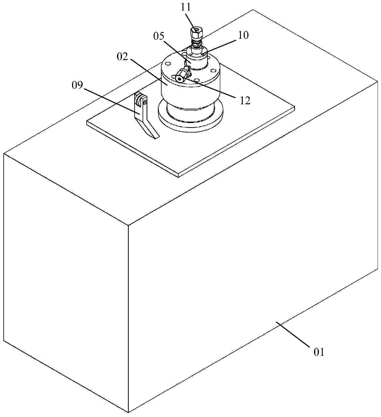
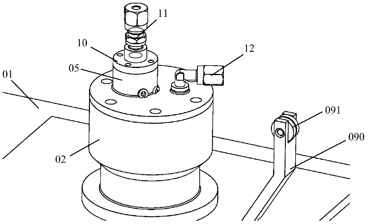
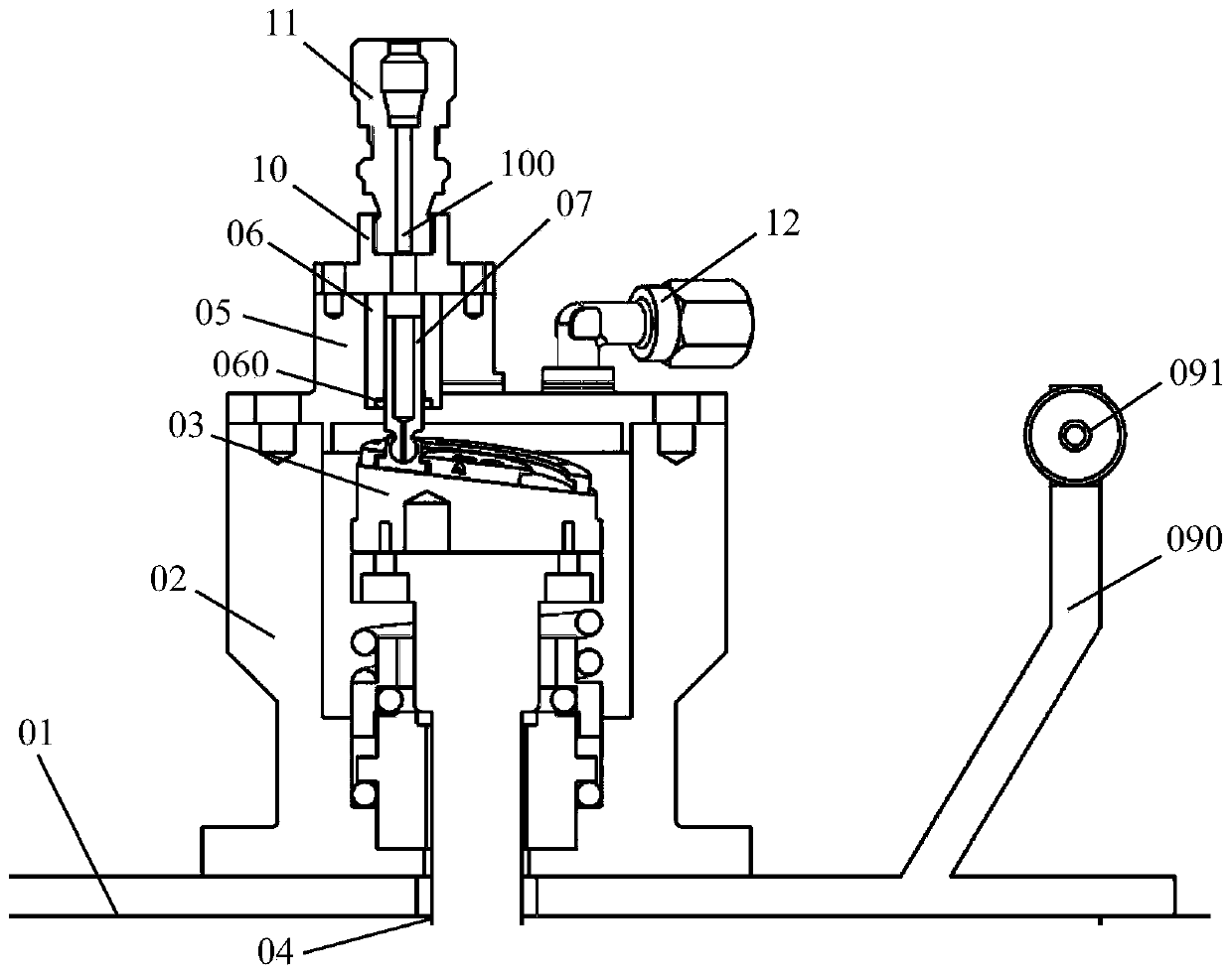
[0068] See attached figure 1 to attach Figure 7 , the embodiment of the present invention discloses a plunger pump motion wear and leakage measurement test bench that can apply centrifugal force, including: bench body 01, main cavity body 02, rotating part 03, driving part 04, plunger cavity body 05, liner Set 06, plunger 07 and screw 08;

[0069] The main cavity 02 is fixed on the top surface of the table body 01;

[0070] The rotating part 03 is rotatabl...


PUM


Abstract

The invention discloses a plunger pump motion abrasion and leakage measuring testbed capable of exerting centrifugal force. The testbed is characterized in that a main cavity body is fixed to the topsurface of a testbed body, a rotating part is rotationally connected in a cavity of the main cavity body, a driving part is arranged in the testbed body and is used for driving the rotating part to rotate, a plunger cavity body is fixedly arranged at the top of the main cavity body in a sealing manner, a lining is sleeved in a cavity of the plunger cavity body, a layer of resin fills the space between the inner wall of the plunger cavity body and the side wall of the lining, a stepped groove is formed in the lower portion of the inner wall of the lining, a sealing ring is arranged in the stepped groove in a sleeved mode, an oil pumping hole communicating with the stepped groove is formed in the side walls of the lining and the plunger cavity body, a plunger is movably connected into the lining, the bottom of the plunger is connected with the rotating part, the plunger moves up and down under the driving of the rotating part in a reciprocating mode, a screw penetrates through the side wall of the plunger cavity body and is fixedly connected with the side wall of the lining, and the screw is connected with a force applying component. According to the testbed, the defect that a traditional testbed lacks centrifugal force consideration during the leakage amount and the plunger abrasion testing is overcome, the simulation effect is good, and the test precision is high.

Description

technical field [0001] The invention relates to the technical field of plunger motion simulation tests, in particular to a plunger pump motion wear and leakage measurement test bench capable of applying centrifugal force. Background technique [0002] At present, plungers are mainly used in pumps or compressors to transfer fluids. The swash plate axial piston pump mainly includes the main shaft, cylinder body, plunger, sliding shoe, return plate, swash plate, etc.; its working principle is: driven by the motor, the main shaft drives the cylinder body to rotate through the spline connection, and the cylinder body rotates. The body drives the plunger to rotate, and the plunger reciprocates in the cylinder bore under the action of the swash plate and the return plate. The plunger head is equipped with a sliding shoe. Due to the action of the return plate, the bottom of the sliding shoe is always kept in contact with the swash plate. . In order to achieve precise switching bet...

Claims


Application Information

Patent Timeline
Patent Type & Authority Patents(China)
IPC IPC(8): F04B51/00G01M13/00G01M3/04
CPCF04B51/00G01M3/04G01M13/00
Inventor 付剑王明康邓红革赵江澳刘继
Owner BEIHANG UNIV
Learn More