
A port cargo stacking crane

A technology of goods and cranes, which is applied in the field of stacking cranes, can solve the problems that goods cannot be placed quickly and orderly, and the operation is complicated, so as to achieve the effect of quick placement

Active Publication Date: 2020-08-25
温岭市城北广进鞋业有限公司
View PDF1 Cites 0 Cited by
  • Summary
  • Abstract
  • Description
  • Claims
  • Application Information

AI Technical Summary

Problems solved by technology

[0002] For example, the publication number CN206108732U is a kind of building pendant tower, comprising a support frame, the bottom of the support frame is provided with a motor, the top of the support frame is provided with a horizontal solar panel, and the bottom of the solar panel is provided with blades. The blades are installed on the side of the supporting frame through the rotating shaft, and the rotating shaft is connected with a generator. The bottom of the supporting frame is provided with a storage battery, an inverter and a transformer. The inverter, transformer and motor are connected in series; the disadvantage of this is that the operation is complicated and the goods cannot be placed quickly and orderly

Method used


Image

  • A port cargo stacking crane
  • A port cargo stacking crane
  • A port cargo stacking crane

Examples


specific Embodiment approach 1

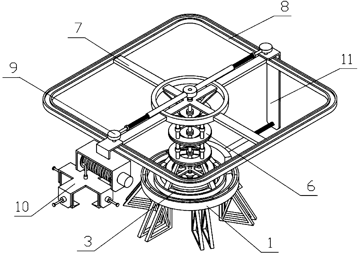
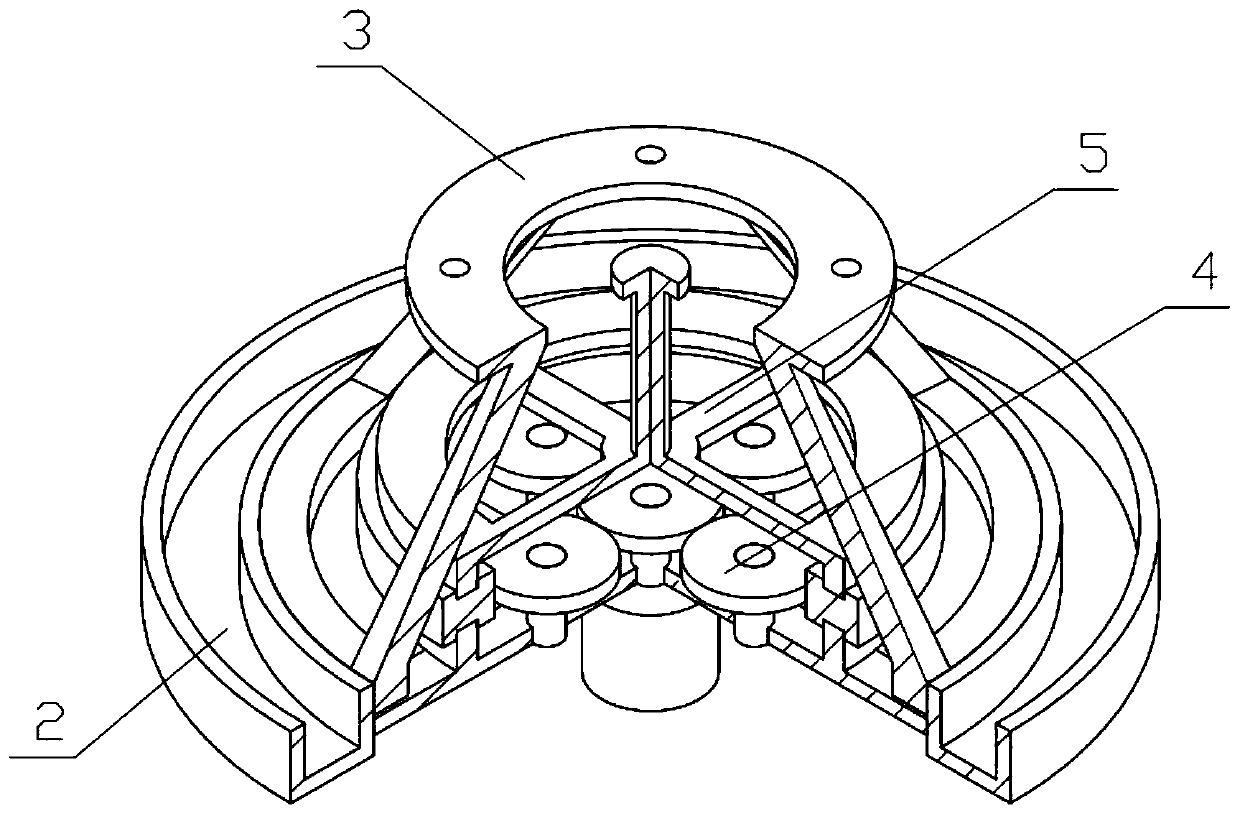
[0036] Combine below Figure 1-13Describe this embodiment, a port cargo stacking crane, including a supporting base 1, a rotating bracket 2, a mounting bracket 3, a planetary mechanism 4, a driving mechanism 5, a supporting bracket 6, a supporting top frame 7, a rectangular rail 8, and a pushing mechanism 9. The hoisting mechanism 10 and the counterweight mechanism 11, the supporting chassis 1 is rotatably connected with a rotating bracket 2, the rotating bracket 2 is fixedly connected with a mounting bracket 3, the rotating bracket 2 is provided with a planetary mechanism 4, and the driving mechanism 5 is fixedly connected On the planetary mechanism 4, a plurality of supporting brackets 6 are fixedly connected between the mounting bracket 3 and the supporting top frame 7, and the supporting brackets 6 are sequentially connected end to end, the driving mechanism 5 and the supporting bracket 6 are connected by transmission, and the supporting top frame 7 is fixedly connected. T...

specific Embodiment approach 2

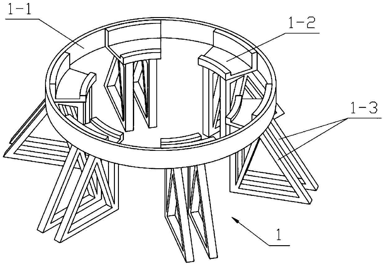
[0038] Combine below Figure 1-13 Describe this embodiment, this embodiment will further explain Embodiment 1, the support chassis 1 includes a chassis ring 1-1, a circular arc track 1-2 and a support foot 1-3, and the chassis ring 1-1 is internally fixed A plurality of circular arc tracks 1-2 are connected, and a plurality of circular arc tracks 1-2 form a rotating track, and a plurality of circular arc tracks 1-2 are fixedly connected with two supporting feet 1-3, and the rotating bracket 2 is rotatably connected to multiple In the rotating track composed of two circular arc tracks 1-2, the rotating bracket 2 is transmission-connected to the output shaft of the drive motor Ⅰ.

specific Embodiment approach 3

[0040] Combine below Figure 1-13 Describe this embodiment, this embodiment will further explain the second embodiment, the installation bracket 3 includes the installation bottom plate 3-1, the support rod 3-2 and the installation top plate 3-3, the installation bottom plate 3-1 is fixedly connected to the rotating bracket 2, a plurality of support rods 3-2 are fixedly connected between the installation bottom plate 3-1 and the installation top plate 3-3.


PUM


Abstract

The invention relates to a stacking hoisting tower, in particular to a port cargo stacking tower. The hoisting tower comprises a supporting bottom frame, a rotary supporting frame, an installing supporting frame, a planetary mechanism, a driving mechanism, supporting frames, a supporting top frame, a rectangular rail, a pushing mechanism, a hoisting mechanism and a weighing mechanism. The hoistingtower has the advantages that the using height of a device can be changed through the mutual accumulation of multiple supporting frames between the supporting bottom frame and the supporting top frame, the using height of the device can be adjusted by rotating the rotary supporting frame, the driving mechanism is driven to rotate through the planetary mechanism, multiple transmission shafts are driven to rotate by the driving mechanism, the pushing mechanism is driven to slide in the rectangular rail by the transmission shafts, the hoisting mechanism and the weighing mechanism are pushed to move by the pushing mechanism under the limitation by the pushing mechanism, and cargo is orderly and rapidly placed by the hoisting mechanism due to the fact that there exists straight edges on the rectangular rail.

Description

technical field [0001] The invention relates to a stacking crane, in particular to a port cargo stacking crane. Background technique [0002] For example, the publication number CN206108732U is a kind of building pendant tower, comprising a support frame, the bottom of the support frame is provided with a motor, the top of the support frame is provided with a horizontal solar panel, and the bottom of the solar panel is provided with blades. The blades are installed on the side of the supporting frame through the rotating shaft, and the rotating shaft is connected with a generator. The bottom of the supporting frame is provided with a storage battery, an inverter and a transformer. The inverter, transformer and motor are connected in series; the disadvantage of this is that the operation is complicated and the goods cannot be placed quickly and orderly. Contents of the invention [0003] The object of the present invention is to provide a port cargo stacking crane, which i...

Claims


Application Information

Patent Timeline
Patent Type & Authority Patents(China)
IPC IPC(8): B66C23/16B66C23/62B66C23/84
CPCB66C23/163B66C23/62B66C23/84
Inventor 赵起龙
Owner 温岭市城北广进鞋业有限公司
Learn More