Conveying arranging device

A technology of conveying device and mounting plate, applied in packaging and other directions, can solve the problems of easy dumping, unsuitable materials for packing after sorting, and inability to use automatic equipment for packing, etc., to avoid easy dumping.

Inactive Publication Date: 2019-11-08
DONGGUAN KAILEDI NUMERICAL CONTROL SCI & TECH CO LTD
View PDF1 Cites 0 Cited by
  • Summary
  • Abstract
  • Description
  • Claims
  • Application Information

AI Technical Summary

Problems solved by technology

[0002] With the development of the national economy and the improvement of industrial technology, the requirements for the efficiency and stability of the product packaging production line are getting higher and higher. For the filling production line of plastic cup materials with a large upper end and a smaller lower end, the front-end filling equipment is in continuous high-speed operation. When the material is crowded during the packing and conveying process, it is particularly easy to dump. Many yogurts are packaged in plastic cups with a large upper end and a small lower end, which makes it impossible to use automatic equipment for material packing
[0003] In order to solve the above-mentioned technical problems, the Chinese patent application publication number CN202272480U discloses a continuous cup feeding positioning device, which is characterized in that the device is provided with two variable-speed timing belts beside the conveyor belt, and the running axis of the timing belts is vertical On the horizontal plane, the two synchronous belts are respectively driven by their respective servo motors, and cup levers are respectively installed on the two synchronous belts, and a cup opening is formed between adjacent cup levers. The two synchronous belts have the same number The distance between the holding cup openings is the same; the positions of the two timing belts in the length direction of the conveyor belt are the same, and a continuously operating cup spacing mechanism is provided in front of the two timing belts to make the cups Keep the same distance when entering the synchronous belt area; but this structure is only suitable for online filling or capping stations, not suitable for packing materials after sorting

Method used


Image

  • Conveying arranging device
  • Conveying arranging device
  • Conveying arranging device

Examples


Embodiment Construction

[0029] The technical solutions of the various embodiments of the present invention will be clearly and completely described below in conjunction with the accompanying drawings. Obviously, the described embodiments are only part of the embodiments of the present invention, not all of them; based on the embodiments of the present invention, All other embodiments obtained by persons of ordinary skill in the art without creative efforts fall within the protection scope of the present invention.

[0030] In the description of the present invention, it should be noted that the terms "center", "upper", "lower", "left", "right", "vertical", "horizontal", "inner", "outer" etc. The indicated orientation or positional relationship is based on the orientation or positional relationship shown in the drawings, and is only for the convenience of describing the present invention and simplifying the description, rather than indicating or implying that the referred device or element must have a ...


PUM


Abstract

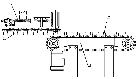
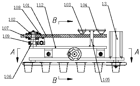
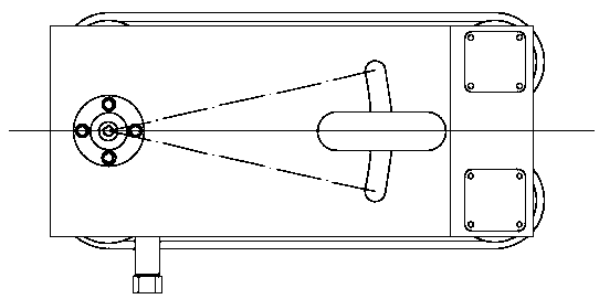
The invention discloses a conveying arranging device. The device comprises an O belt arranging device, an unpowered conveying device and a brush device. The upper edge of the material is used for conveying, two O belt transmission devices symmetrically arranged are adopted for hanging the upper edge of the material, during O belt rotation, the material is driven to forwards move, an air cylinder is adopted to push the two O belt transmission devices to swing back and forth at the same time, alignment with an arranging channel is carried out, and arranging tasks are finished. A screw adjustingdevice is used for adjusting the interval between the two O belt transmission devices, the device can adapt to multiple material specifications, after the material enters the unpowered conveying device, the upper edge of the material is hung on the unpowered conveying device, a brush on the brush device is used for pushing the material backwards, the material is arranged in order, in the materialconveying process, the manner of supporting the upper edge of the material is adopted for conveying forwards, and the problem that the material is conveyed in a standing manner, and is prone to toppling over is solved.

Description

technical field [0001] The invention relates to the technical field of packaging machinery, in particular to a conveying and sorting device. Background technique [0002] With the development of the national economy and the improvement of industrial technology, the requirements for the efficiency and stability of the product packaging production line are getting higher and higher. For the filling production line of plastic cup materials with a large upper end and a smaller lower end, the front-end filling equipment is in continuous high-speed operation. When the material is crowded during the packing and conveying process, it is particularly easy to dump. Many yogurts are packaged in plastic cups with a large upper end and a small lower end, which makes it impossible to use automatic equipment for material packing. [0003] In order to solve the above technical problems, the Chinese patent application publication number CN202272480U discloses a continuous cup feeding positio...

Claims


Application Information

Patent Timeline
Patent Type & Authority Applications(China)
IPC IPC(8): B65B35/30
CPCB65B35/30
Inventor 蒋太武邱广文陈马鑫
Owner DONGGUAN KAILEDI NUMERICAL CONTROL SCI & TECH CO LTD
Why Eureka
Try Eureka