
Scissor type lifting device for fan

A lifting device, scissor-type technology, applied in the direction of lifting device, lifting frame, etc., can solve the problems of unable to carry out transportation transfer, large wind volume, and power consumption occasions that are not suitable for transfer, so as to avoid high-altitude installation operations, reduce difficulty, The effect of improving stability

Pending Publication Date: 2019-11-05
首帆动力科技股份有限公司
View PDF0 Cites 0 Cited by
  • Summary
  • Abstract
  • Description
  • Claims
  • Application Information

AI Technical Summary

Problems solved by technology

Existing small wind turbines are generally fixedly installed on the top of the support pole with a higher height to achieve a better windward effect and a larger windward volume. However, this installation structure requires high-altitude installation work on the one hand, which increases the difficulty of wind turbine installation. On the other hand, it cannot be transported and transferred, and it is not suitable for power consumption occasions that often need to be transferred

Method used


Image

  • Scissor type lifting device for fan
  • Scissor type lifting device for fan
  • Scissor type lifting device for fan

Examples


Embodiment Construction

[0018] Below in conjunction with specific embodiment, further illustrate the present invention. It should be understood that these examples are only used to illustrate the present invention and are not intended to limit the scope of the present invention. In addition, it should be understood that after reading the teachings of the present invention, those skilled in the art can make various changes or modifications to the present invention, and these equivalent forms also fall within the scope defined by the appended claims of the present application.

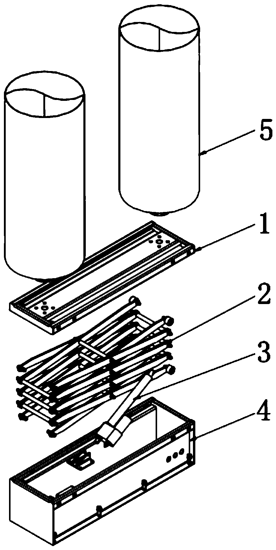
[0019] Such as figure 1 A fan scissor lifting device shown includes a fan mounting base 1 , a scissor arm lifting assembly 2 , a lifting drive device 3 and a fixed base 4 . The scissor arm lifting assembly 2 is installed on the fixed base 4, the fan mounting base 1 is installed on the scissor arm lifting assembly 2, and the scissor arm lifting assembly 2 is driven by the lifting drive device 3 for lifting adjustment.

[0020]...


PUM


Abstract

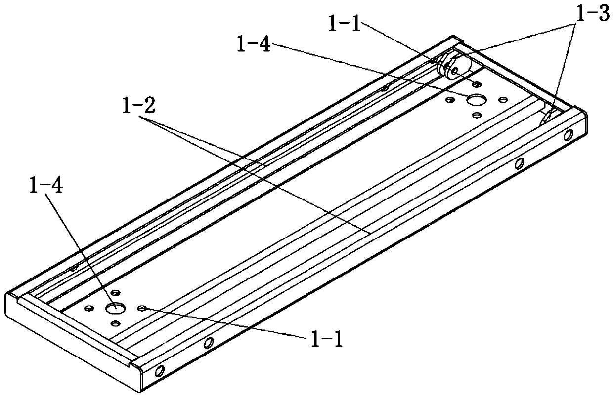
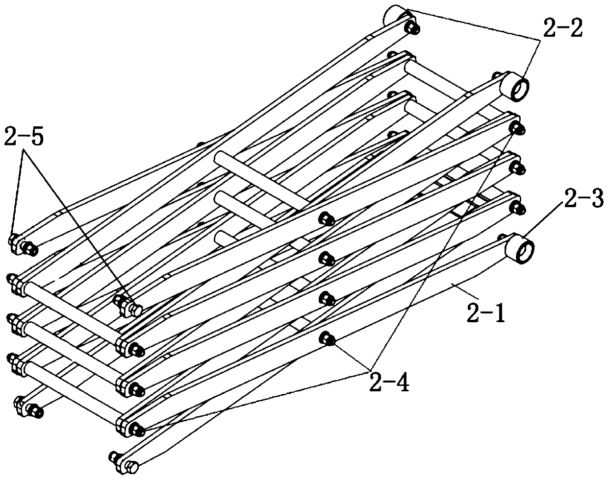
The invention relates to a scissor type lifting device for a fan. The device comprises a fan mounting base, a scissor arm lifting assembly, a lifting driving device and a fixing base, wherein first sliding roller guide grooves are formed in the two sides of the fan mounting base, first scissor arm fixing lugs are arranged on the two sides of one end of the fan mounting base, second sliding rollerguide grooves are formed in the two sides of the fixing base, second scissor arm fixing lugs are arranged on the two sides of one end of the fixing base, top supporting arms at one end of the scissorarm lifting assembly are connected with the first scissor arm fixing lugs through a shaft, bottom supporting arms are in shaft connection with the second scissor arm fixing lugs, first sliding rollersare mounted on top supporting arms at the other end of the scissor arm lifting assembly, second sliding rollers are mounted on bottom supporting arms, the first sliding rollers are arranged in the first sliding roller guide grooves correspondingly, the second sliding rollers are arranged in the second sliding roller guide grooves, and the scissor arm lifting assembly is driven by a lifting driving device to ascend and descend in a height direction. According to the device, initial mounting height of the fan can be reduced, and the conveying and transferring of the fan can be facilitated.

Description

technical field [0001] The invention belongs to the technical field of installation of wind power generation equipment, in particular to a scissor-type lifting device for wind turbines. Background technique [0002] A wind turbine is a power device that converts wind energy into mechanical energy, which drives the rotor to rotate, and finally outputs alternating current. It has the advantages of no fuel, no radiation, and no pollution. Existing small wind turbines are generally fixedly installed on the top of the support pole with a higher height to achieve a better windward effect and a larger windward volume. However, this installation structure requires high-altitude installation work on the one hand, which increases the difficulty of wind turbine installation. On the other hand, it cannot be transported and transferred, and is not suitable for power consumption occasions that often need to be transferred. Contents of the invention [0003] The technical problem to be ...

Claims


Application Information

Patent Timeline
Patent Type & Authority Applications(China)
IPC IPC(8): B66F7/08B66F7/28B66F7/06
CPCB66F7/08B66F7/28B66F7/0666
Inventor 李云强杜剑峰
Owner 首帆动力科技股份有限公司
Learn More