
A screw driven lifting platform with auxiliary lifting blocks

A technology of lifting table and screw rod, which is applied in the field of lifting table, can solve the problems that the lifting table is not easy to keep in the same position for a long time, the lifting table cannot be raised immediately, and the driving force of the screw rod increases, so as to reduce the driving power and cargo The up and down lifting table is convenient and the effect of reducing the driving force

Active Publication Date: 2017-06-16
杭州光羽新材料科技有限公司
View PDF6 Cites 0 Cited by
  • Summary
  • Abstract
  • Description
  • Claims
  • Application Information

AI Technical Summary

Problems solved by technology

Moreover, the hydraulic oil of the hydraulic mechanism is easy to leak, and the lifting table is not easy to keep in the same position for a long time
The traditional horizontal screw scissors lift table is driven by the screw rod directly pulling the horizontal movable end of the shear arm. When the angle between the scissor arm and the horizontal plane is less than 20 degrees, the driving force of the screw rod increases sharply, causing the lifting table to move. unable to rise immediately

Method used


Image

  • A screw driven lifting platform with auxiliary lifting blocks
  • A screw driven lifting platform with auxiliary lifting blocks
  • A screw driven lifting platform with auxiliary lifting blocks

Examples


Embodiment Construction

[0022] The specific implementation manner of the present invention will be described in detail below in conjunction with the accompanying drawings.

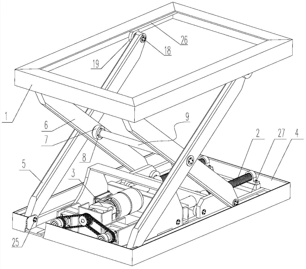
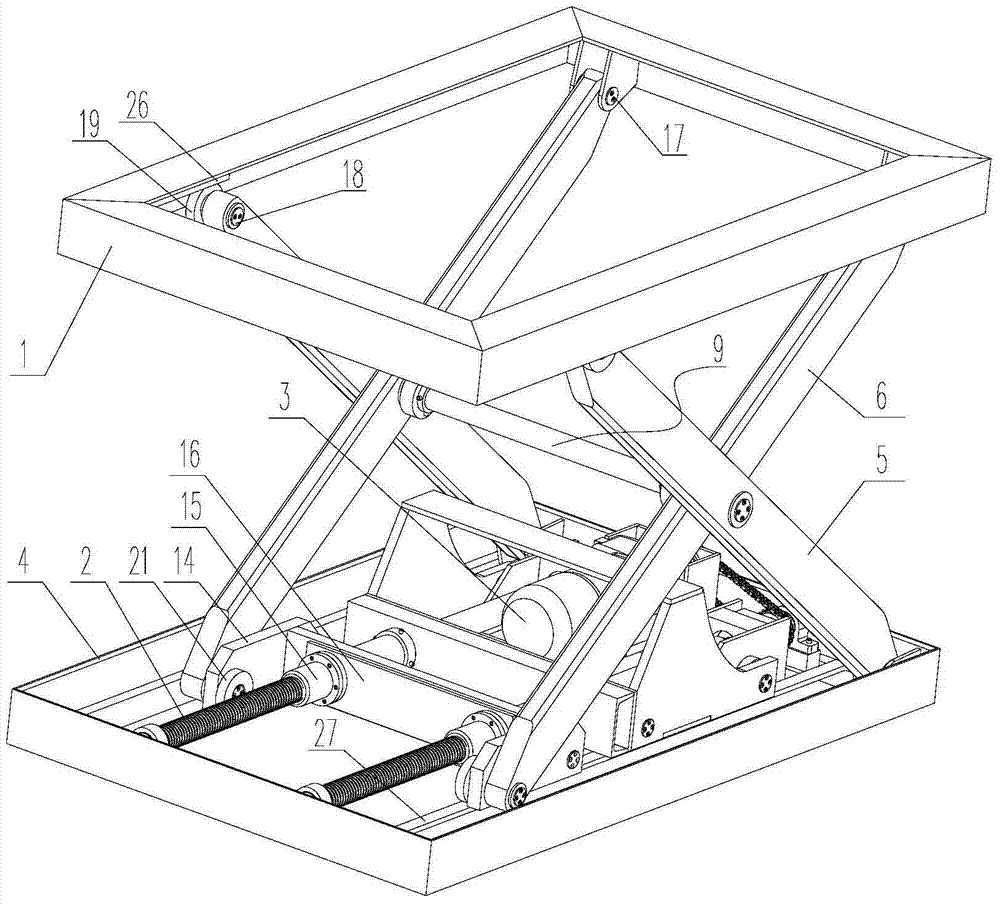
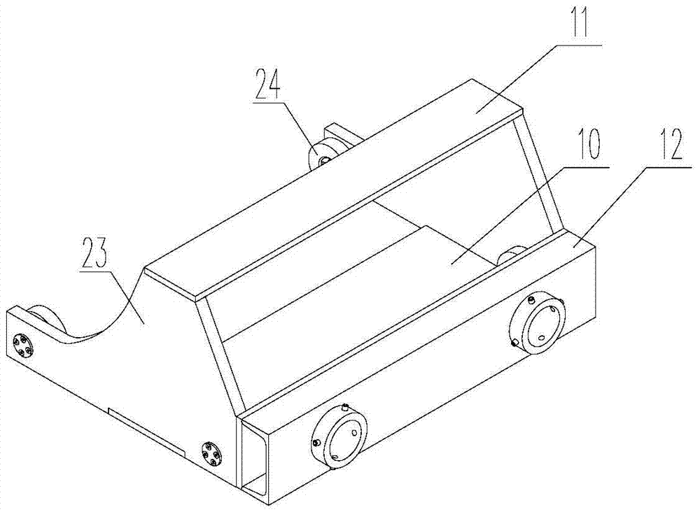
[0023] Such as figure 1 , figure 2 Shown is a screw driven lifting platform with auxiliary lifting blocks, the lifting platform includes an upper frame 1, a lower frame 4, two outer support arms 5, two inner support arms 6, two lifting plates 23, Two push rods 13, a U-shaped frame 14 and a nut connecting plate 16, the middle part of the outer support arm 5 and the inner support arm 6 are respectively hinged to form a scissor structure, and are connected together by setting a cross long axis 9. The outer support arm 5 and the inner support arm 6 are respectively arranged on the inner walls of the left and right ends of the lower frame 4 and the upper frame 1, and the lower rails 27 are respectively arranged on both sides of the lower frame 4, and the left and right sides of the lower frame 4 The wall is hinged with the lower en...


PUM


Abstract

The invention relates to a lead screw driving lifting platform with an auxiliary raising block. The lifting platform comprises a lower frame, an upper frame, two outer supporting arms and two inner supporting arms, and further comprises two raising plates, two pushing rods and a U-shaped frame. The front side faces of the two raising plates are each provided with a curve face or an inclined face. A connecting beam is arranged between the two raising plates to fixedly connecting the two raising plates. The bottoms of the two raising plates are provided with raising plate wheels respectively. The raising plate wheels make contact with the upper surface of a lower rail. The two pushing rods are fixedly connected to the rear end of the connecting beam. The connecting plate is arranged between the two pushing rods to connect the two pushing rods. A middle connecting plate of the U-shaped frame is provided with two axial holes. The portions, at the front end of the connecting plate, of the pushing rods are arranged in the axial holes in a penetrating mode. Lower idler wheels are arranged at the bottom of the U-shaped frame. The two side faces of the U-shaped frame are provided with hinge points respectively to be hinged to the lower ends of the two inner supporting arms. The lead screw driving lifting platform is safe and reliable, the driving power is lowered, and the lifting range is enlarged.

Description

technical field [0001] The invention relates to a lifting platform, in particular to a screw driven lifting platform with auxiliary lifting blocks. Background technique [0002] The lifting platform is an indispensable basic equipment in the modern machinery industry. At present, the scissor lifting platform driven by the inclined hydraulic cylinder is more mature and has better use effect. However, when the lifting angle is about 10 degrees in actual use, the driving force It is about 3 times of the load, and when the lifting angle reaches 60 degrees, the driving force is close to the load. And the hydraulic oil of the hydraulic mechanism is easy to leak, and the lifting platform is not easy to keep in the same position for a long time. The traditional horizontal screw scissors lift table is driven by the screw rod directly pulling the horizontal movable end of the shear arm. When the angle between the scissor arm and the horizontal plane is less than 20 degrees, the drivi...

Claims


Application Information

Patent Timeline
Patent Type & Authority Patents(China)
IPC IPC(8): B66F7/06B66F7/28
CPCB66F7/0608B66F7/28
Inventor 娄海峰王勇竺志超马善红
Owner 杭州光羽新材料科技有限公司
Learn More