
Self-locking structure used for television bracket

A technology of self-locking structure and TV bracket, which is applied to parts of color TV, parts of TV system, TV, etc. It can solve the problem of not being able to turn and adjust the TV orientation angle as needed, unfavorable tightening of screws and nuts, and affecting the viewing effect, etc. problem, to achieve the effect of improving connection stability, facilitating stable installation, and facilitating flip adjustment angle

Inactive Publication Date: 2019-11-01
贵州商学院
View PDF8 Cites 1 Cited by
  • Summary
  • Abstract
  • Description
  • Claims
  • Application Information

AI Technical Summary

Problems solved by technology

[0003] However, when the existing TV bracket structure is in use, most of the TV sets are fixedly installed on the wall, so that they can only maintain a parallel state with the wall, and cannot turn over and adjust the orientation angle of the TV as required, which has poor adaptability and affects the viewing effect. It cannot be self-locked to ensure the stability of the adjustment. At the same time, the existing bracket is easy to interfere with the bracket when installing the TV, which is not conducive to tightening screws and nuts. The convenience needs to be improved.

Method used


Image

  • Self-locking structure used for television bracket
  • Self-locking structure used for television bracket
  • Self-locking structure used for television bracket

Examples


Embodiment Construction

[0030] The following will clearly and completely describe the technical solutions in the embodiments of the present invention in conjunction with the accompanying drawings in the embodiments of the present invention; obviously, the described embodiments are only part of the embodiments of the present invention, not all embodiments, based on The embodiments of the present invention and all other embodiments obtained by persons of ordinary skill in the art without making creative efforts belong to the protection scope of the present invention.

[0031] In the description of the present invention, it should be noted that the orientations or positional relationships indicated by the terms "upper", "lower", "inner", "outer", "top / bottom" etc. are based on the orientations shown in the drawings Or positional relationship is only for the convenience of describing the present invention and simplifying the description, but does not indicate or imply that the device or element referred t...


PUM


Abstract

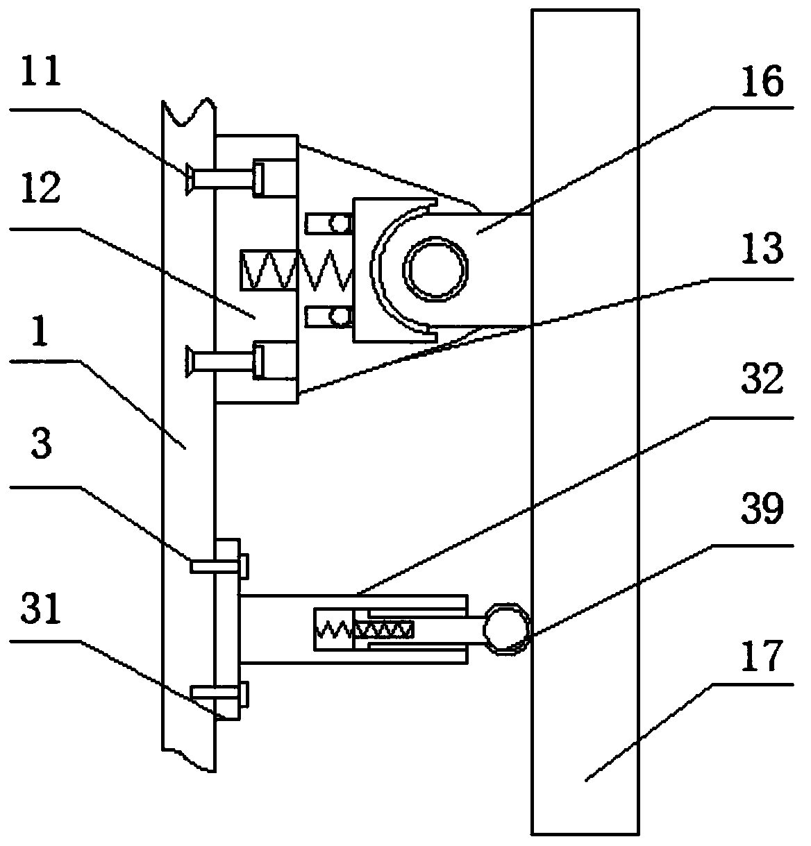
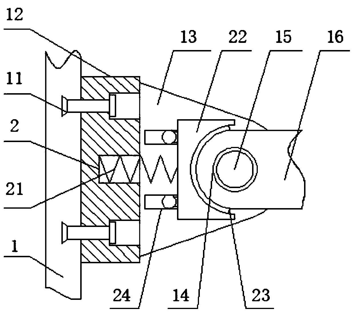
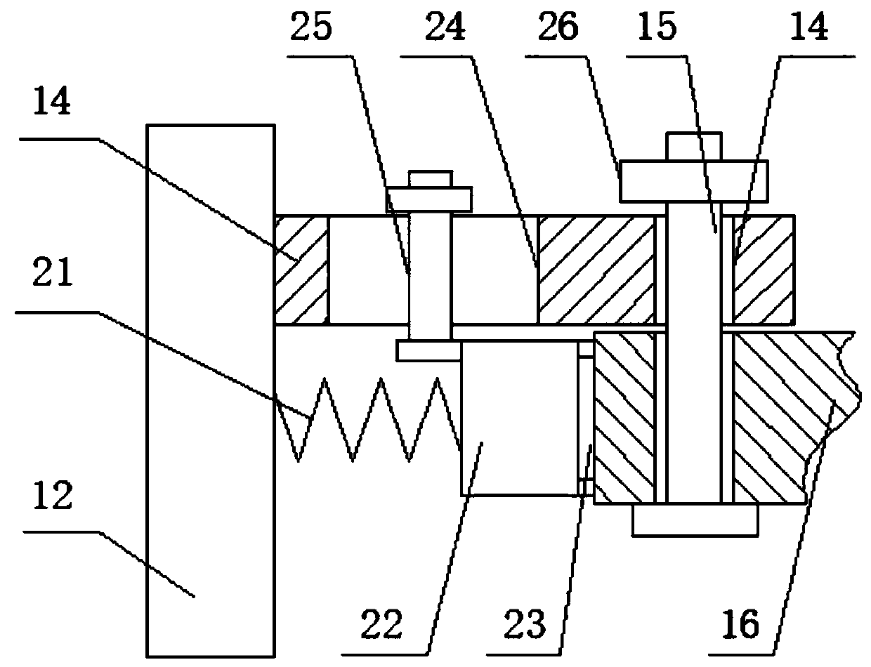
The invention discloses a self-locking structure used for a television bracket and belongs to the field of television brackets. The self-locking structure used for the television bracket comprises a wall. A fixing base is fixedly mounted at the upper end of the outer surface of the wall through expansion bolts. The rear side of the outer surface of the fixing base is fixedly connected with a sideplate. A mounting circular hole is formed in the rear end of the interior of the side plate. A connecting plate is rotationally mounted on the inner side surface of the mounting circular hole througha supporting shaft. The rear side surface of the connecting plate is fixedly connected with a television. A spring groove is formed in the rear side surface of the fixing base. A puller spring is fixedly mounted on the inner side surface of the spring groove. An arc-shaped locking base is fixedly mounted on the rear side surface of the puller spring. The inner side surface of the arc-shaped locking base is connected to the front end of the outer surface of the connecting plate through a locking friction plate in a pressed mode. Thus, the using convenience and stability can be greatly improved,and the safety performance and high efficiency are guaranteed.

Description

technical field [0001] The invention relates to the field of TV brackets, and more specifically relates to a self-locking structure for TV brackets. Background technique [0002] In current daily life and work, the use of televisions is very common, and most of the existing televisions are liquid crystal display screens with a relatively small thickness. In order to facilitate management, they are generally installed on the wall through brackets. [0003] However, when the existing TV bracket structure is in use, most of the TV sets are fixedly installed on the wall, so that they can only maintain a parallel state with the wall, and cannot turn over and adjust the orientation angle of the TV as required, which has poor adaptability and affects the viewing effect. Self-locking cannot be performed to ensure the stability of the adjustment. At the same time, the existing bracket is easy to interfere with the bracket when installing the TV, which is not conducive to tightening s...

Claims


Application Information

Patent Timeline
Patent Type & Authority Applications(China)
IPC IPC(8): F16M13/02F16M11/04F16M11/10H04N5/225
CPCF16M13/02F16M11/043F16M11/10F16M2200/021H04N23/00
Inventor 张俊
Owner 贵州商学院
Learn More