Full-automatic punching machine of LED lamp tube

An LED lamp, fully automatic technology, applied in metal processing and other directions, can solve the problems of complex structure, unreasonable structural design, low degree of automation, etc., to achieve the effect of scientific and reasonable structure, convenient and fast adjustment, and high degree of automation

Pending Publication Date: 2019-11-01
广州英固特智能装备有限公司
View PDF0 Cites 1 Cited by
  • Summary
  • Abstract
  • Description
  • Claims
  • Application Information

AI Technical Summary

Problems solved by technology

Most of the punching processing in the prior art is manual operation, the degree of automation is low, and the processing efficiency is low, and most of the processing equipment is for punching the two ends of the LED lamp tube, which is not suitable for the middle part of the LED lamp tube. Punching processing, at the same time, it cannot be punched for different types of processed pipes, the adjustment performance of the overall equipment is poor, the applicability is low, the production efficiency is low, and the structural design is unreasonable, the structure is complex, the failure rate is high, and the maintenance is inconvenient, etc. Wait

Method used


Image

  • Full-automatic punching machine of LED lamp tube
  • Full-automatic punching machine of LED lamp tube
  • Full-automatic punching machine of LED lamp tube

Examples


Embodiment Construction

[0025] The technical solution of this patent will be further described in detail below in conjunction with specific embodiments.

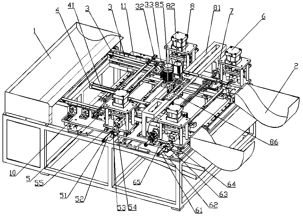
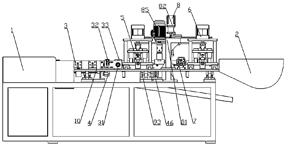
[0026] see Figure 1-7 , a fully automatic punching machine for LED lamp tubes, comprising a machine platform, a feed hopper 1, a feeding assembly 3, a punching assembly, a turning assembly 7 and a discharge hopper 2; the feed hopper 1, the feeding assembly 3, the punching assembly, Both the turnover assembly 7 and the discharge hopper 2 are arranged on the machine platform. A fixed frame 10 and a mobile frame 11 are respectively arranged on both sides of the middle part of the machine, and a transport mechanism 4 is arranged between the fixed frame 10 and the mobile frame 11; the punching assembly includes a first punching die 5 and a second punching die. Hole die 6, a turning assembly 7 is arranged between the first punching die 5 and the second punching die 6, and a pipe middle punching assembly 8 is arranged between the first punching die 5 an...


PUM


Abstract

The invention discloses a full-automatic punching machine of an LED lamp tube. The full-automatic punching machine comprises a machine table, a feeding hopper, a feeding assembly, a punching assembly,an overturning assembly and a discharging hopper, wherein the feeding hopper, the feeding assembly, the punching assembly, the overturning assembly and the discharging hopper are arranged on the machine table. The two sides of the middle of the machine table are respectively provided with a fixed machine frame and a movable machine frame, and a carrying mechanism is arranged between the fixed machine frame and the movable machine frame; the punching assembly comprises a first punching die and a second punching die, the overturning assembly is arranged between the first punching die and the second punching die, and a pipe middle punching assembly is arranged between the first punching die and the overturning assembly; and the pipe middle punching assembly is arranged above the carrying mechanism, and the feeding assembly, the first punching die, the overturning assembly, the second punching die and the discharging hopper are sequentially arranged on the fixed machine frame and the movable machine frame. The full-automatic punching machine is suitable for automatic punching processing of the LED lamp tubes of different types, energy-saving, convenient to maintain, simple in structure, high in automation degree and wide in applicability.

Description

technical field [0001] The invention relates to a lamp tube processing equipment, in particular to a full-automatic punching machine for LED lamp tubes. Background technique [0002] At present, the processing and positioning openings on LED lamp tubes in the industry still adopt a semi-automatic method combining manual and mechanical. LED lamp tubes are usually tubular structures with openings at both ends. The tube supplies power and seals the lamp tube. In the process of installing the plug and the power supply, it is necessary to open a mounting hole on the LED lamp tube that matches the installation structure of the plug and the power supply to facilitate installation. However, there are some new LED lamp tubes in the middle An opening structure is also provided to facilitate the fixed installation of the LED light tube and provide stability. Most of the punching processing in the prior art is manual operation, the degree of automation is low, and the processing effici...

Claims


Application Information

Patent Timeline
Patent Type & Authority Applications(China)
IPC IPC(8): B26F1/14B26F1/02B26D7/02B26D7/06B26D7/32
CPCB26D7/02B26D7/0625B26D7/32B26F1/0053B26F1/02B26F1/14
Inventor 莫词英
Owner 广州英固特智能装备有限公司
Why Eureka
Try Eureka