Golf mark scraper

A technology for golf balls and markers, which is applied to golf balls, golf accessories, sports accessories, etc., which can solve the problems of inconvenience, easy loss, and easy deviation, etc., to avoid easy irregularity, neat and accurate marking, and easy to carry Effect

Active Publication Date: 2019-10-29
尹恺文
View PDF6 Cites 3 Cited by
  • Summary
  • Abstract
  • Description
  • Claims
  • Application Information

AI Technical Summary

Problems solved by technology

For example, Chinese patent application number CN201127825Y discloses a golf ball marker, which includes a clip, a pivot joint, and an elastic element. The body is provided with a hole for placing a paintbrush. The above two patents both use a paintbrush to scribe along the groove or groove after fixing the golf ball. However, in practical applications, such a scriber will produce There are many problems: 1. Compared with the mechanical method of drawing lines, manual operation using brushes has problems such as irregular lines, uneven lengths and thicknesses, etc., which are prone to deviations in golf; 2. The fixture and brush are separated from each other, which is easy to Lost, causing inconvenience; 3. The way of drawing lines by hand requires a lot of preparation time before sports, such as jamming-positioning-marking repeated operations twice, and in sports, if too many lost balls are played, supplements are required. When the new ball draws the line, the human body will be in a state of tension due to a lot of exercise, and the paintbrush is easy to shake. At the same time, it is impossible to re-draw the line due to the time limit during the game

Method used


Image

  • Golf mark scraper
  • Golf mark scraper
  • Golf mark scraper

Examples


Embodiment Construction

[0040] In order to make the object, technical solution and advantages of the present invention clearer, the present invention will be further described in detail below in combination with specific embodiments and with reference to the accompanying drawings. It should be understood that these descriptions are exemplary only, and are not intended to limit the scope of the present invention. Also, in the following description, descriptions of well-known structures and techniques are omitted to avoid unnecessarily obscuring the concept of the present invention.

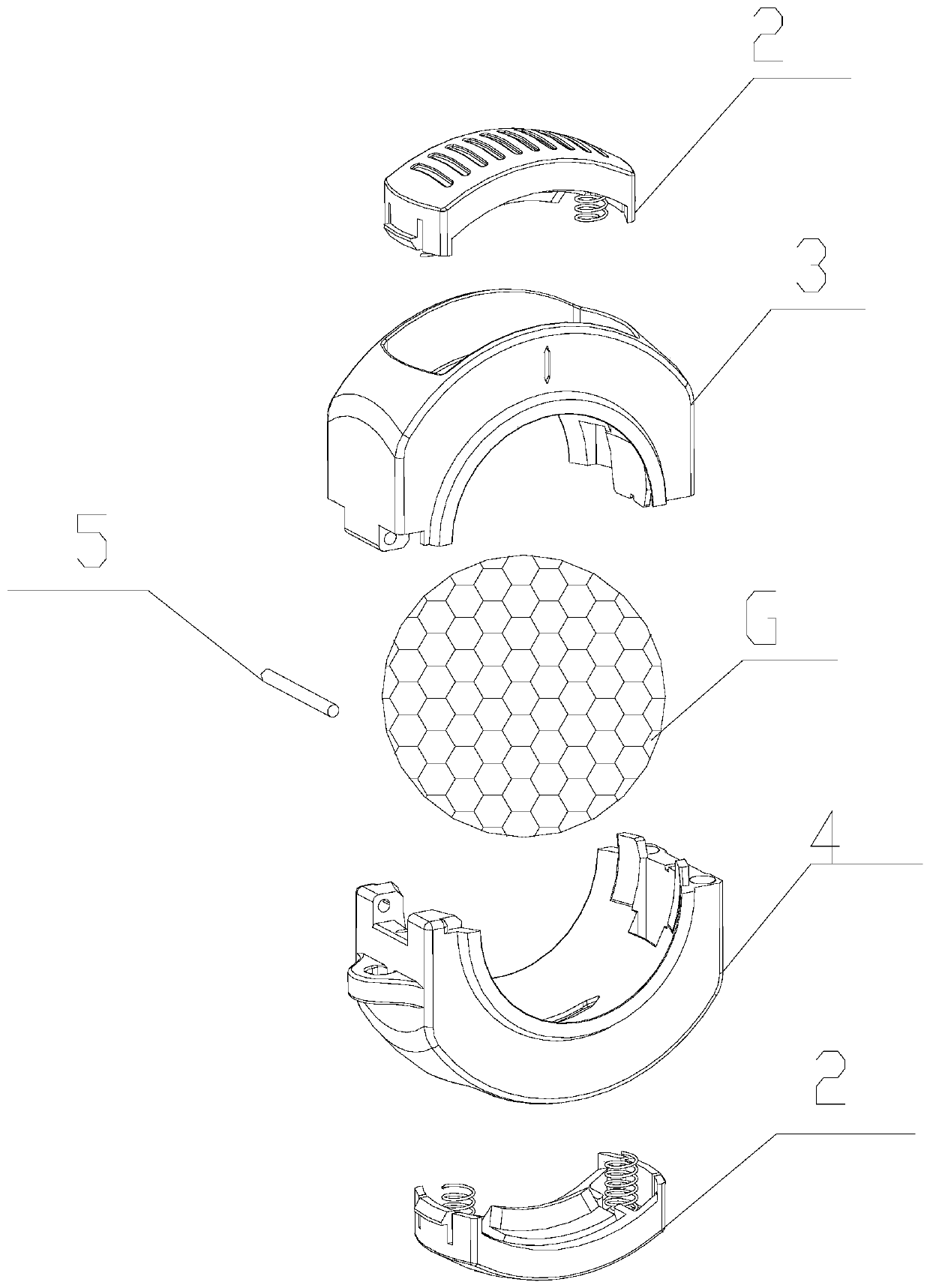
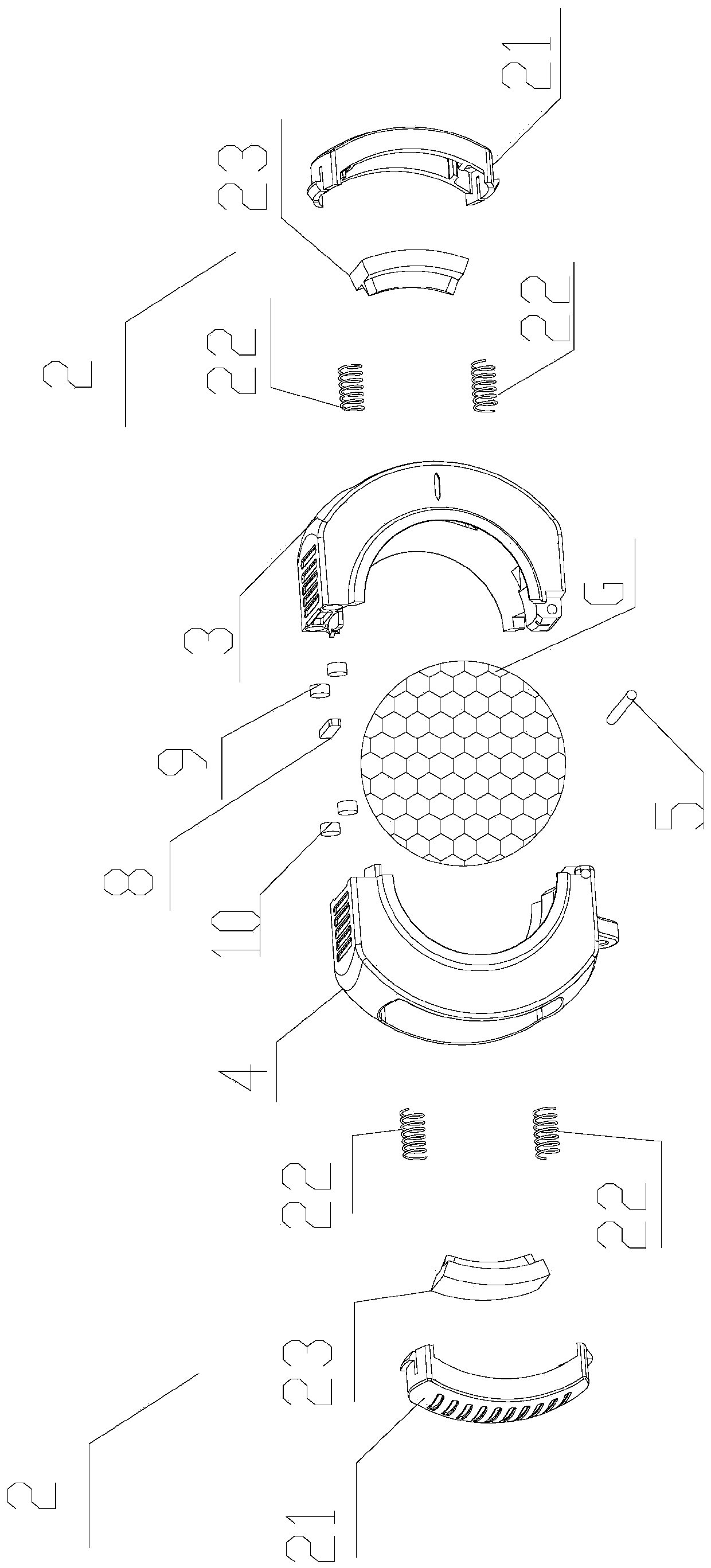
[0041] Such as Figure 1-8 As shown, the golf ball marker proposed by the present invention includes a clip 1, and the clip 1 includes a No. 1 clip body 3 and a No. 2 clip body 4 connected by a pivot shaft 5. The clip 1 The inner clamping surface has a groove surface 6 matched with the golf ball surface, which is characterized in that it also includes a marker 2;

[0042] The outer walls of the No. 1 buckle body 3 and t...


PUM


Abstract

The invention relates to a golf mark scraper comprising a buckle clamp and a marker; the buckle clamp comprises a first buckle clamp body and a second buckle clamp body, wherein the first buckle clampbody and the second buckle clamp body are connected through a pivot, the inner clamp surface of the buckle clamp is provided with a clamping groove surface matched with the spherical surface of a golf ball, one end of the first buckle clamp body and one end of the second buckle clamp body are hinged through a pivoting shaft, and the other end of the first buckle clamp body and the other end of the second buckle clamp body are connected with magnetic force; both the first buckle clamp body and the second buckle clamp body are respectively provided with a buckle clamp groove, the bottom of thebuckle clamp groove is provided with a straight ruler containing a scribing groove, and the two ends of the buckle clamp groove are symmetrically provided with compression part mortises; the marker comprises a compression part, springs and an ink box; the compression part cooperates with the buckle clamp groove, the two ends of the compression part are provided with compression part tenons cooperating with the compression part mortises, the ink box and the two springs are fixed in the groove in the bottom of the compression part, the other ends of the two springs are connected with the first buckle clamp body and the second buckle clamp body respectively, an arc ink nozzle is arranged in the middle of the ink box, the ink nozzle communicates with the ink box and corresponds to the scribinggroove. According to the golf mark scraper in the invention, a pen is not needed, double-sided scribing is achieved, and the golf mark scraper is more attractive and convenient to carry.

Description

technical field [0001] This invention relates to golf equipment, and more particularly, to golf ball markers. Background technique [0002] Golf is a highly technical and precise sport. However, the key to precise technical requirements lies in: when the ball is hit by a high-speed moving club head when hitting the ball, the flight direction of the ball must be accurate; Hole the ball on an undulating path. Therefore, the starting point of this precision sport is "aiming". [0003] The purpose of the existing golf ball marking device is to allow users to draw lines on the ball of the golf ball, so as to facilitate the hitter to aim and increase the stability when hitting the ball. For example, Chinese patent application number CN201127825Y discloses a golf ball marker, which includes a clip, a pivot joint, and an elastic element. The body is provided with a hole for placing a paintbrush. The above two patents both use a paintbrush to scribe along the groove or groove aft...

Claims


Application Information

Patent Timeline
Patent Type & Authority Applications(China)
IPC IPC(8): A63B57/00
CPCA63B57/00
Inventor 尹恺文
Owner 尹恺文
Why Eureka
Try Eureka