


Quick Research
Generate reliable direction feasibility study reports for your R&D in just a few steps.

Technical Q&A
Discover and master advanced knowledge NOW. Basics, ideas, possibilities, all at once.

Find Solutions
As an expert in R&D theories, this can generate solutions to your technical problems instantly.

Evaluate Feasibility
Analyze your overall solution with one click, know your potential R&D risks in advance.

Monitor Landscape
Get weekly tech updates, stay abreast of the latest tech innovations and key insights.
Resin molded body and blue light cut laminated body
A technology for resin moldings and resin layers, applied in synthetic resin layered products, coatings, optics, etc., can solve problems such as difficult to show the influence of resin molding physical properties, achieve the suppression of haze rise and good shielding properties Effect
- Summary
- Abstract
- Description
- Claims
- Application Information
AI Technical Summary
Problems solved by technology
Method used
Image

Examples
Embodiment 1
[0296] (formation of resin layer)
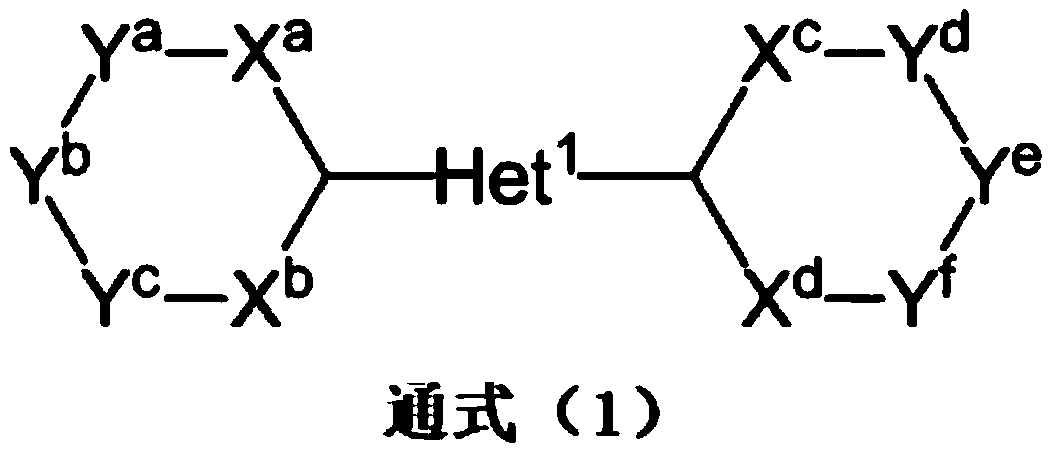
[0297] The pellets of polyethylene terephthalate (PET) dried at 160°C for 8 hours and the compound (A) having the following structure as a compound represented by the general formula (1) were mixed and put into extrusion machine. Melt-kneading was carried out at a melting temperature of 280° C. to prepare a masterbatch containing pellets as the compound (A).
[0298] After that, PET pellets dried at 160° C. for 8 hours were mixed with the compound (A)-containing pellet masterbatch obtained above so that the content of the compound (A) in the resin layer became 0.7% by mass, and mixed at 280° C. Melt-kneading was carried out at °C, and a resin layer as a film with a thickness of 100 μm was formed by a melt extrusion method.
[0299] [chemical formula 13]
[0300]
[0301] (formation of protective layer)
[0302] On one side of the obtained resin layer, a composition for forming a protective layer 1 containing a urethane resin prepared ...
Embodiment 2~10
[0340] (formation of resin layer)
[0341] The pellets of polyethylene terephthalate (PET) dried at 160° C. for 8 hours and the compound (A) having the above structure were mixed and charged into an extruder. Melt-kneading was carried out at a melting temperature of 280° C. to prepare a masterbatch containing pellets of the compound (A) (compound (A) containing masterbatch pellets).
[0342] After that, PET pellets dried at 160° C. for 8 hours and a masterbatch containing pellets as compound (A) were mixed in such a ratio that the content of compound (A) in the resin layer became the amount described in the following Table 5, and mixed at 280° C. Melt-kneading was carried out at °C, and a resin layer as a film with a thickness of 100 μm was formed by a melt extrusion method.
[0343] (formation of protective layer)
[0344] On the surface of the resin layer obtained above, the protective layer 1 containing an acrylic resin was formed by the following method.
[0345] The ma...
Embodiment 11
[0350] A resin layer having a thickness of 100 μm was formed in the same manner as in Example 1.
[0351] A protective layer containing polysiloxane was formed on the surface of the obtained resin layer by a sol-gel method.
[0352] That is, first, the components shown in the following Table 6 were mixed to prepare a polysiloxane-containing composition for forming a protective layer.
[0353] Specifically, stirring the aqueous acetic acid solution, 3-glycidoxypropyltrimethoxysilane was dropped into the aqueous acetic acid solution over 3 minutes. Next, tetraethoxysilane was added to the aqueous acetic acid solution over 3 minutes while stirring. Next, stirring was continued for 2 hours. Next, colloidal silica, a chelating agent, and a surfactant were sequentially added to prepare a polysiloxane-containing composition for forming a protective layer.
[0354] [Table 6]
[0355] (parts by mass)
[0356]
[0357] The surface of the resin layer was subjected to corona disch...
PUM
| Property | Measurement | Unit |
|---|---|---|
| thickness | aaaaa | aaaaa |
| thickness | aaaaa | aaaaa |
| transmittivity | aaaaa | aaaaa |
Abstract
Description
Claims
Application Information
 - R&D Engineer
- R&D Manager
- IP Professional
- Industry Leading Data Capabilities
- Powerful AI technology
- Patent DNA Extraction
Browse by: Latest US Patents, China's latest patents, Technical Efficacy Thesaurus, Application Domain, Technology Topic, Popular Technical Reports.
© 2024 PatSnap. All rights reserved.Legal|Privacy policy|Modern Slavery Act Transparency Statement|Sitemap|About US| Contact US: help@patsnap.com