Solar energy cell series structure

A technology of solar cells and series structure, applied in circuits, photovoltaic power generation, electrical components, etc., can solve the problem of waste of cell area

Pending Publication Date: 2019-10-25
CHANGZHOU SHICHUANG ENERGY CO LTD
View PDF0 Cites 0 Cited by
  • Summary
  • Abstract
  • Description
  • Claims
  • Application Information

AI Technical Summary

Problems solved by technology

[0004] In the shingling method, one of the two adjacent cells will block the other cell, which will cause a waste of cell area

Method used


Image

  • Solar energy cell series structure
  • Solar energy cell series structure
  • Solar energy cell series structure

Examples


Embodiment 1

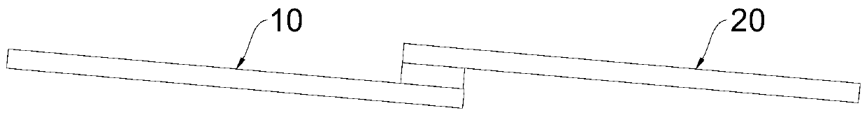
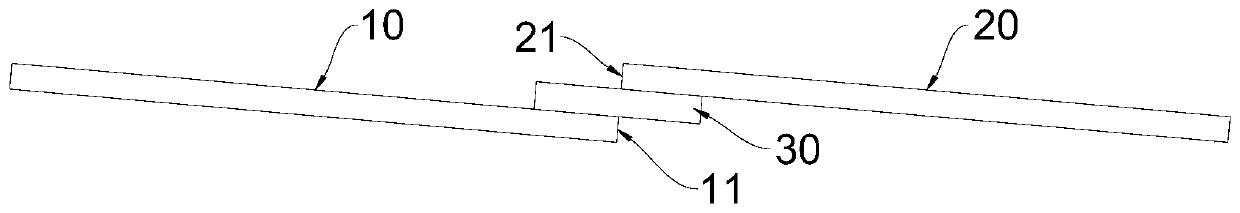
[0030] Such as image 3 As shown, a series structure of solar cells includes two cells 10, 20 laid adjacent to each other, and the two cells 10, 20 are connected in series through a conductive connector 30; the conductive connector 30 is formed by one of the The front of the battery sheet 10 extends to the back of the other battery sheet 20; the edge lines 21, 11 at the opposite ends of the two battery sheets 20, 10 are set up and down, and the edge lines 21, 11 at the opposite ends of the two battery sheets 20, 10 are aligned up and down;

[0031] The front side of the battery sheet 10 whose opposite edge line 11 is located below is connected to the conductive connector 30;

[0032] The back side of the battery sheet 20 on which the opposite edge line 21 is located is connected to the conductive connector 30;

[0033] The opposite end of the cell sheet 20 whose opposite edge line 21 is above is supported by the conductive connector 30 and / or the supporting structure (not sho...

Embodiment 2

[0037] Such as Figure 4 Shown, on the basis of embodiment 1, difference is:

[0038] The sidelines 11, 21 of the opposite ends of the above two battery sheets 10, 20 are straight lines;

[0039] There are a plurality of conductive connectors 30, and the plurality of conductive connectors 30 are sequentially arranged at intervals along the extension direction of the opposite edge lines 11, 21 of the two battery sheets 10, 20; and the plurality of conductive connectors 30 and the two The sidelines 11, 21 of the opposite ends of the battery slices 10, 20 are vertical.

Embodiment 3

[0041] Such as Figure 5 Shown, on the basis of embodiment 1, difference is:

[0042] The sidelines 11, 21 of the opposite ends of the above two battery sheets 10, 20 are straight lines;

[0043] The conductive connector 30 includes: a main body 31 connected to the back of the battery sheet 20, and a plurality of extensions 32 extending from the main body 31 and connected to the front of the battery sheet 10; the plurality of extensions 32 are along the above-mentioned The two battery sheets 10 , 20 are arranged at intervals in sequence toward the extending direction of the edge lines 11 , 21 .


PUM


Abstract

The invention discloses a solar energy cell series structure. The solar energy cell series structure includes two adjacent cells, wherein the two cells are connected in series through a conductive connection member, the conductive connection member extends from a front side of one of the cells to a back side of the other cell, edge lines of opposite ends of the two cells are arranged up and down,and the edge lines of the opposite ends of the two cells are aligned up and down. The solar energy cell series structure is advantaged in that the edge lines of the opposite ends of the two adjacent cells are aligned up and down, density of the cells can be maximized in the horizontal direction, the edge lines of the opposite ends of the adjacent two cells are aligned up and down, that is, the adjacent two cells are not blocked from each other, a problem that one of the adjacent two cells blocks the other cell due to use of the imbricate technology can be avoided, and waste of the cell area isavoided.

Description

technical field [0001] The invention relates to a series structure of solar cells. Background technique [0002] Solar cell modules (also called solar panels, photovoltaic modules) are the core part of the solar power generation system. The solar battery module includes a battery string, and the battery string is composed of a plurality of solar battery slices laid in series in sequence. There are two main connection methods of existing battery strings: tiling and shingling. [0003] In the tiling method, there is a certain distance between two adjacent cells in the horizontal direction (with a conductive connector in between), so the density of cell laying is not maximized. [0004] In the shingling method, one of the two adjacent cells will block the other cell, which will cause a waste of cell area. Contents of the invention [0005] In order to solve the defects in the prior art, the present invention provides a series structure of solar cells, which includes two ad...

Claims


Application Information

Patent Timeline
Patent Type & Authority Applications(China)
IPC IPC(8): H01L31/05
CPCH01L31/0504Y02E10/50
Inventor 常振宇符黎明王伟亮曹育红
Owner CHANGZHOU SHICHUANG ENERGY CO LTD
Why Eureka
Try Eureka