
Road marking machine

A technology of marking machine and car body, applied in the direction of roads, roads, road repair, etc., can solve the problems of unevenness, insufficient thickness of marking lines, and poor quality of marking lines, so as to achieve uniform distribution of paint, eliminate rework phenomenon, and mark beautiful line effect

Inactive Publication Date: 2019-10-25
班戈设备系统(苏州)有限公司
View PDF0 Cites 4 Cited by
  • Summary
  • Abstract
  • Description
  • Claims
  • Application Information

AI Technical Summary

Problems solved by technology

The existing road marking machine is generally pushed by the staff to mark the road, because the speed of different staff pushing the road marking machine is not the same, even sometimes the speed of the same staff pushing the road marking machine is often However, the amount of paint produced by the road marking machine is basically the same, so the speed at which the road marking machine is driven is different, and the distribution of the paint marking the marking line on the road will be uneven, which will greatly affect the marking line. Beautiful; even less paint on the marking line leads to insufficient thickness of the marking line and reworks and adds paint, which affects work efficiency
[0003] In addition, when the construction personnel take a long break during work, the paint in the paint cylinder in the road marking machine will not be released and will remain in the paint cylinder. Over time, the mixed paint in the paint cylinder is prone to precipitation; Wait for construction When the personnel rest and then use the road marking machine to mark the line, the paint flowing out of the line will not be uniform. The uneven paint will easily cause the quality of the marking line to be unqualified, easy to rework or affect the appearance of the marking line

Method used

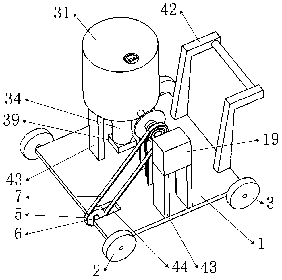
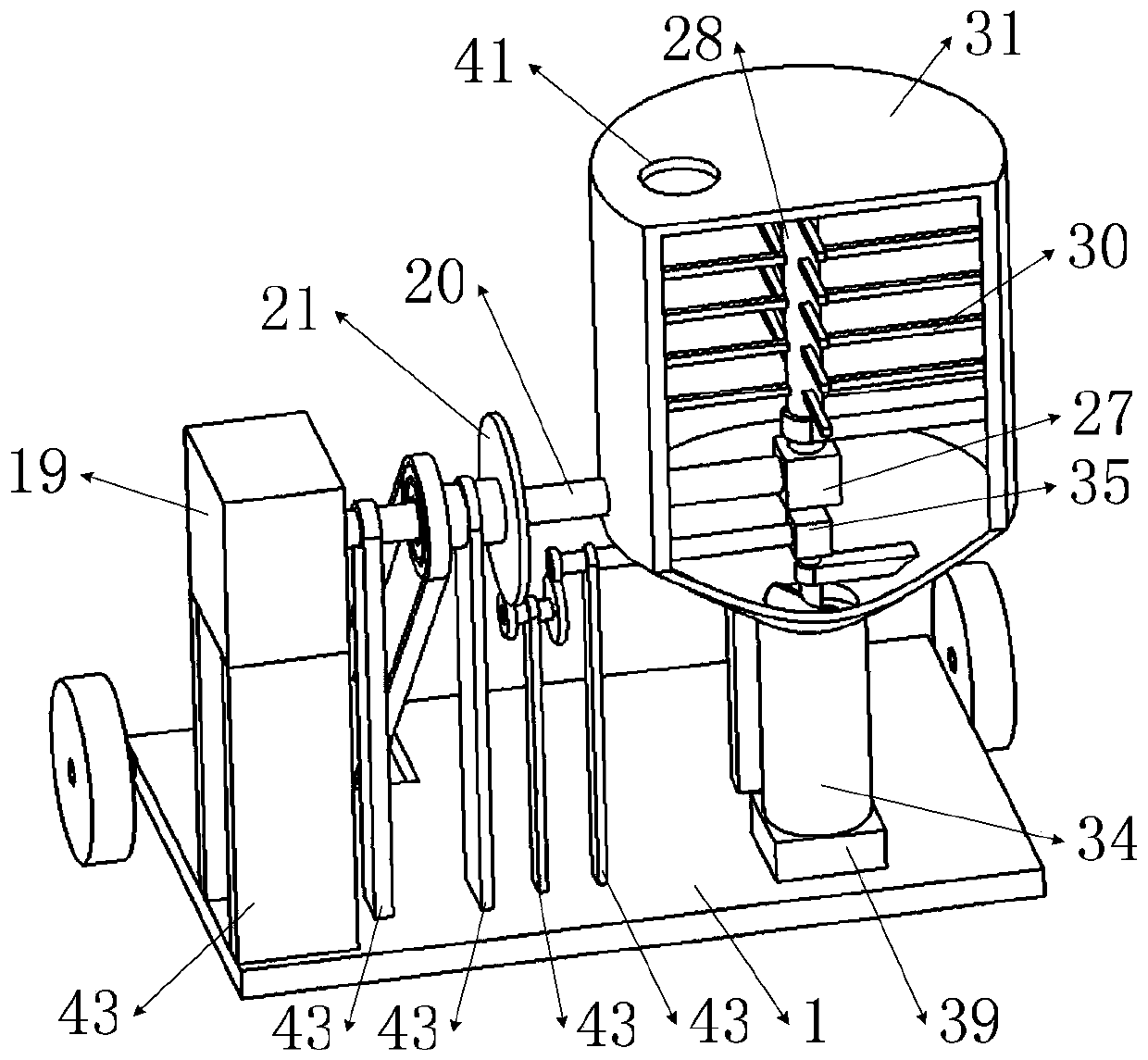
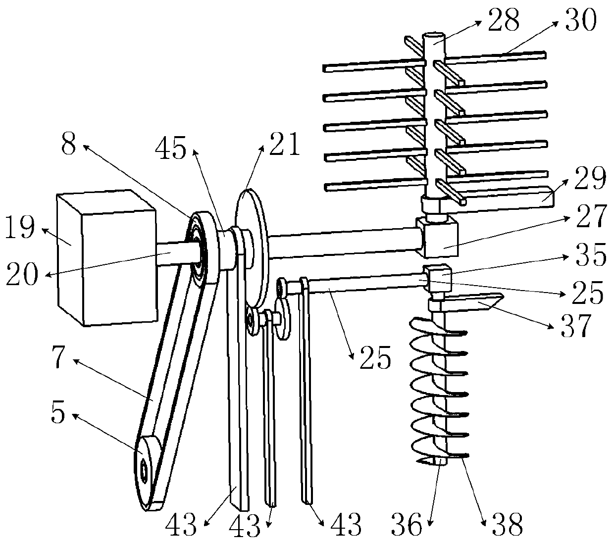

Image

  • Road marking machine
  • Road marking machine
  • Road marking machine

Examples


Embodiment Construction

[0036] The present invention will be described below with reference to the accompanying drawings. The structural proportions of the accompanying drawings are only schematic, and the structural proportions can be determined according to actual needs; however, it should be understood that these descriptions are only exemplary and are not intended to limit the scope of the present disclosure. . Also, in the following description, descriptions of well-known structures and techniques are omitted to avoid unnecessarily obscuring the concepts of the present disclosure. All terms (including technical and scientific terms) used herein have the meaning as commonly understood by one of ordinary skill in the art, unless otherwise defined. It should be noted that terms used herein should be construed to have meanings consistent with the context of the present specification and should not be construed in an idealized or overly rigid manner.

[0037] A road marking machine, which includes a...


PUM


Abstract

The invention belongs to the technical field of marking, and particularly relates to a road marking machine, which comprises a vehicle body, a B one-way ring, an input ring, a slider, a spiral piece,a pressure valve, a nozzle and the like. When the marking machine performs marking operation, under the transcendence of the B one-way ring, the inner ring of the B one-way ring rotates with the outerring of the B one-way ring, so that the forward speed of a front wheel determines the rotation speed of the input ring, the rotation speed of the spiral piece on an F-axis is further determined, andthe amount of paint discharged from a small straight cylinder of the spiral piece per unit time is determined. The forward speed of the vehicle body determines the amount of spray of the nozzle per unit time, which varies along with the forward speed of the vehicle body pushed by construction personnel, so that the spray marking of the nozzle is basically in a uniform state when the vehicle body advances at different speeds, and painted marked lines on the road are evenly distributed, and are attractive. The road marking machine has simple structure and good use effect.

Description

technical field [0001] The invention belongs to the technical field of marking, and particularly relates to a road marking machine. Background technique [0002] At present, pavement marking work is generally required after the road is paved. The existing road marking machine is generally driven by the staff to mark the road surface. Because the speed of different staff pushing the road marking machine is different, even sometimes the speed of the same staff pushing the road marking machine is often However, the amount of paint produced by the road marking machine is basically unchanged, so the speed at which the road marking machine is pushed is different, and the distribution of the paint on the road marking the marking line will be uneven, which will greatly affect the marking line. Beautiful; even if the marking line has less paint, the thickness of the marking line is insufficient and the paint is reworked, which affects the work efficiency. [0003] In addition, when...

Claims


Application Information

Patent Timeline
IPC IPC(8): E01C23/22
CPCE01C23/22
Inventor 李晓强钱理
Owner 班戈设备系统(苏州)有限公司
Learn More