An automatic loading and unloading device for 100-meter rail

A technology for automatic loading and unloading of steel rails, applied in the directions of transportation and packaging, conveyor objects, etc., can solve the problems of bending and torsional deformation of steel rails, low efficiency, reduced work efficiency, etc., to prevent overturning or yaw, reduce manufacturing costs, and improve work efficiency. The effect of efficiency

Active Publication Date: 2020-05-08
NORTHEASTERN UNIV LIAONING
View PDF12 Cites 0 Cited by
  • Summary
  • Abstract
  • Description
  • Claims
  • Application Information

AI Technical Summary

Problems solved by technology

China's railways have entered the "high-speed" era. For passenger trains with a speed of more than 200km per hour, the traditional 25m-long steel rails cannot meet the speed-up requirements at all, and 100-meter-long steel rails must be specially laid
70% of the rails in China come from Anshan Iron and Steel Group, but for the 100-meter rails that are too long, there is no suitable automation equipment for loading and unloading, and multiple people are used to coordinate loading and unloading operations, which is inefficient and prone to multi-directional rails Bending torsion deformation, reducing rail quality
[0003] At present, most of the commonly used loading and unloading systems are transported in the form of cranes. The disadvantage is that at least two people are required to complete the operation, and the parking position needs to be checked; the lifting mechanism uses a winch, and the height of the rails is controlled by ropes. It is prone to deflection and reduces work efficiency; the electromagnet only restrains the vertical direction of the rail, and has no binding force in the horizontal direction, which is easy to cause the rail to dump during transportation or unloading

Method used


Image

  • An automatic loading and unloading device for 100-meter rail
  • An automatic loading and unloading device for 100-meter rail
  • An automatic loading and unloading device for 100-meter rail

Examples


Embodiment Construction

[0017] The specific embodiments of the present invention will be further described below in conjunction with the drawings and technical solutions.

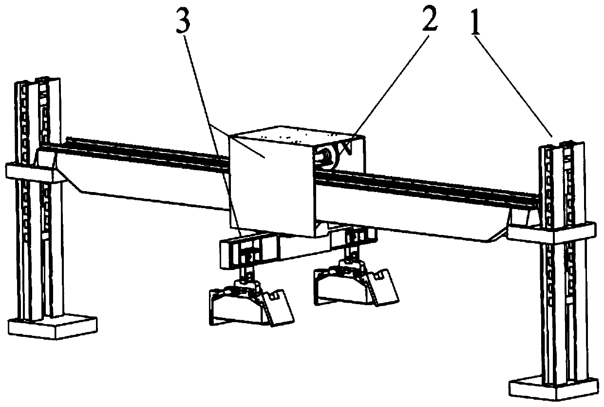
[0018] Such as figure 1 As shown, the present invention includes a lifting module 1, a lateral movement module 2, an electromagnetic adsorption module 3, and a monitoring module. The electromagnetic adsorption module 3 walks on the upper lifting module 1 through the lateral movement module 2, and the submodules of the monitoring module are respectively installed In the first 3 modules.

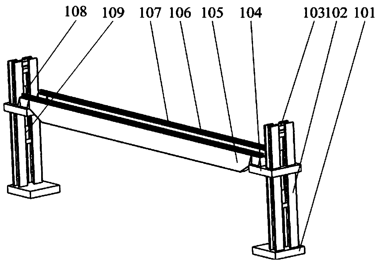
[0019] Such as figure 2 As shown, the lifting module 1 includes two supporting columns 102 respectively installed on the foundation 101. The inner side of each supporting column 102 is provided with an upper lifting hydraulic cylinder 108 and a lower lifting hydraulic cylinder 109, and a large beam connecting plate 104 is sleeved on the outer side. The inner side of the large beam connecting plate 104 is connected to the lower part of the upper liftin...


PUM


Abstract

The invention discloses an automatic loading and unloading device of a hundred-meter steel rail. The device comprises a lifting module, a transverse moving module, an electromagnetic attraction module, and a monitoring module; the electromagnetic attraction module walks on the lifting module through the transverse moving module, sub modules of the monitoring module are arranged on the another three modules, the brand-new design scheme is adopted, and the problems that an existing steel rail loading and unloading device is long in consumed time, low in efficiency, and low in loading and unloading precision and needs manual cooperation can be solved. The device can precisely lift the hundred-meter steel rail attracted by an electromagnet, the hundred-meter steel rail can be rapidly transported, deflection of the hundred-meter steel rail in the transport process can be effectively prevented, and therefore in the stacking process, toppling over is avoided; and the device has the pertinence, is suitable for the work environment of short-stroke lifting and long-stroke transverse moving, and is more efficient and higher in precision compared with an existing device.

Description

Technical field [0001] The invention belongs to the technical field of automatic loading and unloading, and relates to an automatic loading and unloading device for 100-meter rails. Background technique [0002] With the rapid development of my country's transportation technology and the improvement of automation level, the production volume of some industries such as steel metallurgy and heavy machinery manufacturing are facing severe challenges from huge demand. China's railways have entered the "high-speed" era. For passenger trains with speeds exceeding 200km per hour, the use of traditional 25m-long steel rails cannot meet the speed-up requirements, and 100-meter rails must be specially laid. 70% of the domestic steel rails come from Anshan Iron and Steel Group, but for the 100-meter-long rails that are too long, there is no suitable automation equipment for loading and unloading them, and multiple people are used to coordinate the loading and unloading operations, which is ...

Claims


Application Information

Patent Timeline
Patent Type & Authority Patents(China)
IPC IPC(8): B65G47/92
CPCB65G47/92
Inventor 张文笛罗忠马聪刘子嘉杨洪朋王晋雯马赶
Owner NORTHEASTERN UNIV LIAONING
Why Eureka
Try Eureka