Rapid assembling and disassembling die for mold sealing of grouting area of lower portion of assembling type prefabricated wall and using method

A prefabricated wall and assembly technology, applied in the direction of molds, manufacturing tools, ceramic molding machines, etc., can solve the problems of easy grout leakage, difficult sealing of grouting area, and limited grouting time, so as to ensure verticality and even force effect

Active Publication Date: 2019-10-25
CHINA MCC17 GRP
View PDF16 Cites 0 Cited by
  • Summary
  • Abstract
  • Description
  • Claims
  • Application Information

AI Technical Summary

Problems solved by technology

[0003] In order to realize the effective connection and quick installation of the PC wall and the cast-in-place floor, a 20mm high grouting area is reserved under the PC wall. Plugging is a difficult problem. At present, there are mainly two plugging methods: 1. Mortar plugging is used, which is expensive and slow to operate. Due to the influence of the mortar solidification period, the grouting time is limited and the overall construction progress is affected; 2. Square wood blockage, square wood blockage is faster, but limited by factors such as the flatness of cast-in-place ground pouring and grouting pressure, it is extremely easy to leak grout, resulting in waste of grouting materials, and affecting the overall quality and appearance of grouting

Method used


Image

  • Rapid assembling and disassembling die for mold sealing of grouting area of lower portion of assembling type prefabricated wall and using method
  • Rapid assembling and disassembling die for mold sealing of grouting area of lower portion of assembling type prefabricated wall and using method
  • Rapid assembling and disassembling die for mold sealing of grouting area of lower portion of assembling type prefabricated wall and using method

Examples


Embodiment 1

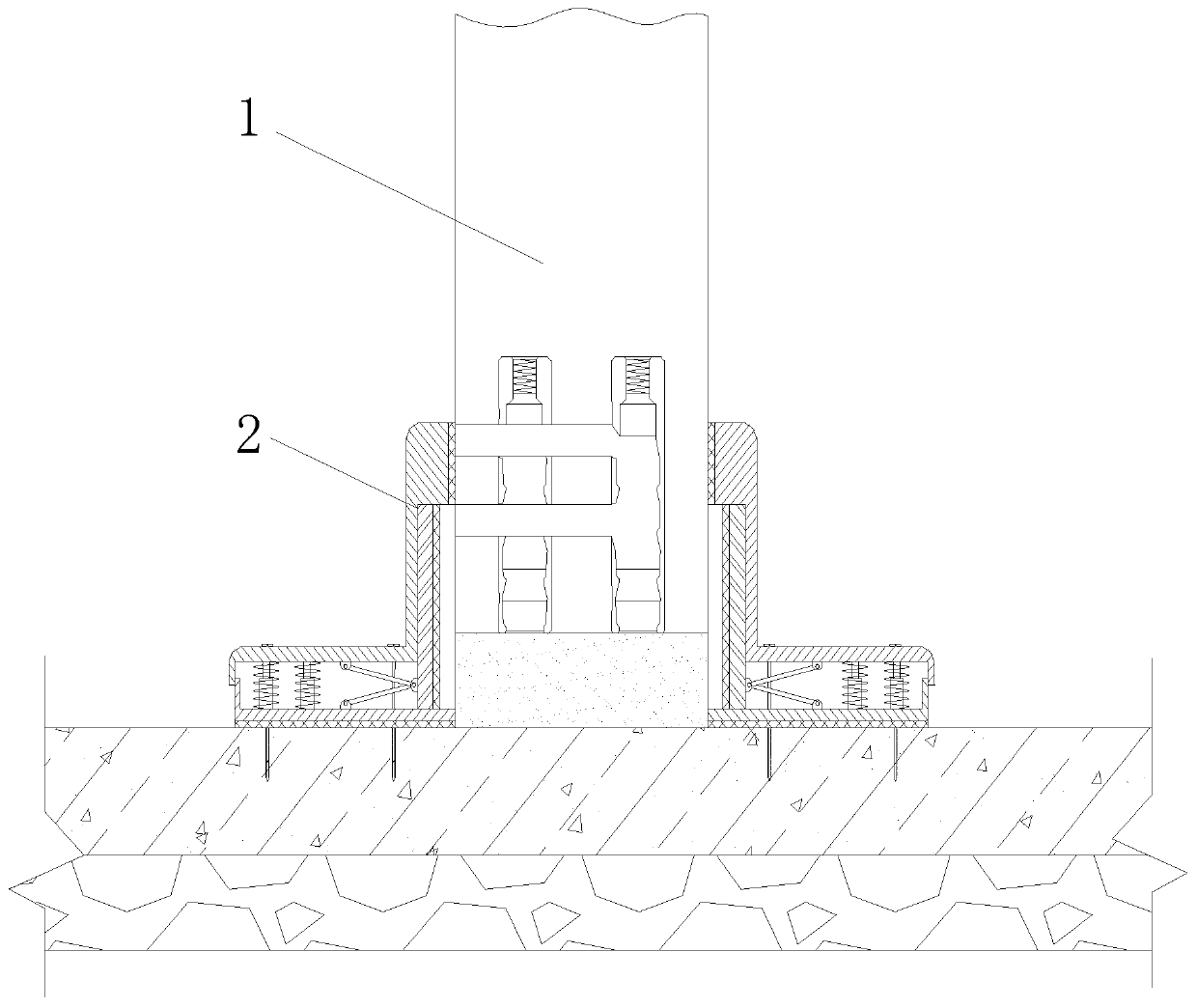
[0036] like Figure 1 to Figure 3 As shown, the sealing mold in the grouting area at the lower part of the prefabricated prefabricated wall is quickly assembled and disassembled.

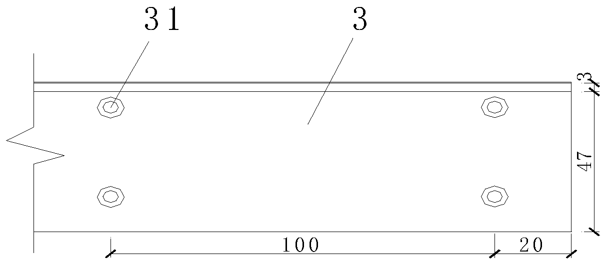
[0037] The L-shaped blocking assembly 2 includes a fixed seat 21 . The fixed seat 21 is provided with a first guide unit 22 . The first guide unit 22 includes a guide column 221 . The outer side of the guide column 221 is sleeved with a compression spring 222 . The end is fixedly connected to the fixed seat 21 , and the free end of the guide post 221 is fixedly connected to the cover plate 3 . When the cover plate 3 is moved downward by an external force, the pressing guide post 221 moves downward to a preset position. When the cover plate 3 is not subjected to external force, the cover plate 3 can be quickly reset to the initial state under the action of the compression spring 222 . A push unit is provided between the cover plate 3 and the fixed seat 21, and the push unit includes two symmetricall...

Embodiment 2

[0040] The difference from Example 1 is: as Figure 4 to Figure 5 As shown, the extrusion part 6 is provided with a second guide unit. The second guide unit includes a positioning plate 61 and a guide rod 62. The positioning plate 61 is located above the cover plate 3. 61 is fixedly connected, and a tension spring 63 is sleeved on the guide rod 62 on the outer side of the fitting portion 23. The elastic force of the tension spring 63 is smaller than that of the compression spring 222, and one end of the tension spring 63 is fixedly connected with the positioning plate 61, and the tension spring 63 is fixedly connected to the positioning plate 61. The other end of the extension spring 63 is fixedly connected to the fitting portion 23 . The extrusion member 6 is guided by the guide rod 62 , and the deflection of the extrusion member 6 is avoided by using the elastic force of the extension spring 63 less than the elastic force of the compression spring 222 .

Embodiment 3

[0042] The difference from Example 2 is: as Image 6 and Figure 8 As shown, a scraping groove 232 is opened in the fitting part 23 at the top of the installation groove 231, and a cleaning unit is arranged in the scraping groove 232. The cleaning unit includes a brush 8, a brush handle 9 and a return spring 10, and the brush 8 is fixedly connected to the One end of the brush handle 9, the end of the brush 8 away from the brush handle 9 is fixedly connected with the scraper 11, the other end of the brush handle 9 extends to the outside of the scraping groove 232, the return spring 10 is sleeved on the outside of the brush handle 9 and one end is It is fixedly connected with the brush handle 9 , and the other end of the return spring 10 is fixedly connected with the fitting portion 23 . After the mold is removed, use the downward movement of the brush handle 9 to clean the surface of the elastic sealing gasket 7 or the extrusion part 6 by the brush 8 and the scraper 11 in sequ...


PUM


Abstract

The invention discloses a rapid assembling and disassembling die for mold sealing of a grouting area of the lower portion of an assembling type prefabricated wall and a using method and belongs to thetechnical field of prefabricated wall grouting mold sealing. The rapid assembling and disassembling die comprises two L-shaped blocking-off assemblies which comprise fixing bases correspondingly. A first guide unit and a fitting portion integrally connected are arranged on each fixing base. A cover plate is connected to each fixing base through the corresponding first guide unit. A pushing unit is arranged between each cover plate and the corresponding fixing base. Coaxial locating holes are formed in the cover plates and the fixing bases correspondingly. A locating part is arranged in the locating holes located in the cover plates and the fixing bases in common. An installing groove is formed in one side wall, back to the corresponding cover plate, of each fitting portion. An extruding part connected with the corresponding pushing unit is arranged in each installing groove. Elastic sealing pads are bonded to the bottom faces of the fixing bases, the side walls, back to the cover plates, of the extruding parts, and the side walls, provided with installing grooves, of the fitting portions correspondingly. According to the die, rapid and precise blocking off and locating can be achieved, meanwhile, the planeness and the perpendicularity of cast-in-place concrete of the prefabricated wall and the bottom grouting area can be effectively ensured, the repeated utilization rate is high, and the construction time and the construction cost are saved.

Description

technical field [0001] The invention belongs to the technical field of prefabricated wall grouting and sealing moulds, and in particular relates to a quick assembly and disassembly mould for a grouting area sealing mould at the lower part of a prefabricated prefabricated wall and a use method. Background technique [0002] The prefabricated structure means that the components are industrially produced in the factory and transported to the site for direct assembly. The components are standardized in the factory to achieve standardized quality, which is conducive to on-site dust reduction, noise reduction, reduction of solid waste generation, reduction of on-site personnel allocation, and reduction of turnover material allocation, so as to achieve green construction on site. The prefabricated components of the external wall have their own insulation layer, and the construction of the main building does not require traditional external scaffolding, which is more convenient and ...

Claims


Application Information

Patent Timeline
Patent Type & Authority Applications(China)
IPC IPC(8): B28B1/14B28B7/00B28B7/22
CPCB28B1/14B28B7/0058B28B7/22
Inventor 王波陈健
Owner CHINA MCC17 GRP
Why Eureka
Try Eureka