
A support device after skin implantation

A technology of supporting device and supporting frame, applied in medical science, physiotherapy, hospital bed, etc., can solve problems such as inability to raise limbs with pillows

Inactive Publication Date: 2021-02-19
THE FIRST AFFILIATED HOSPITAL OF ARMY MEDICAL UNIV
View PDF11 Cites 0 Cited by
  • Summary
  • Abstract
  • Description
  • Claims
  • Application Information

AI Technical Summary

Problems solved by technology

[0003] The present invention intends to provide a support device after skin implantation to solve the technical problem that the pillow in the prior art cannot raise the limbs to the corresponding height according to the actual needs of the patient

Method used


Image

  • A support device after skin implantation
  • A support device after skin implantation
  • A support device after skin implantation

Examples


Embodiment 1

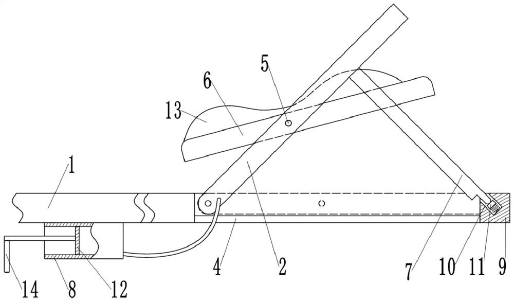
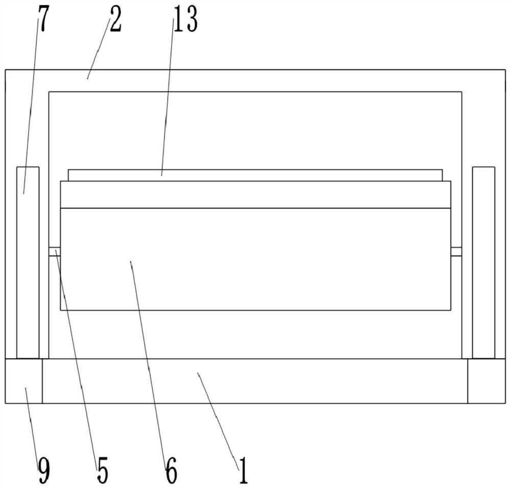
[0035] as attached figure 1 Shown: a supporting device after skin implantation, including a supporting frame 1 and a hinged frame 2 hinged on the supporting frame 1, and the supporting frame 1 is fixedly connected with at least four legs 3 by bolts. Such as figure 2 As shown, the hinged frame 2 is located at the right end of the supporting frame 1, the upper surface of the hinged frame 2 is flush with the upper surface of the supporting frame 1, the lower surface of the hinged frame 2 is higher than the lower surface of the supporting frame 1, and the right end of the supporting frame 1 The extension plate 4 used to support the hinged frame 2 is fixedly welded. There is a cavity on the extension plate 4, and the rotation range of the hinged frame 2 is 0-135°, here 45° is taken as an example; the hinged frame 2 rotates through the shaft hole A backing plate 6 for supporting the patient's limb is connected. The support frame 1 is provided with an inflatable mechanism for driv...

Embodiment 2

[0040] Such as Figure 5 , Figure 6 As shown, the difference between this embodiment and Embodiment 1 is that the two ends of the backing plate 6 are respectively fixedly engaged with a rotating shaft 5, and the hinge frame 2 is provided with a shaft hole for the rotating shaft 5 to pass through; Figure 6 As shown, the outer ring gear 19 is fixedly clamped on the rotating shaft 5 at the left end of the backing plate 6, and the inner ring gear 20 for engaging with the outer ring gear 19 is integrally formed in the shaft hole, and the left end of the rotating shaft 5 and the shaft hole A second elastic reset member 21 is arranged between the bottom, and the second elastic reset member 21 is a compression spring, the left end of the compression spring is welded to the shaft hole, and the right end of the compression spring is offset against the rotating shaft 5; the left end of the shaft hole is provided with a smooth section, The axial length of the smooth section is greater ...


PUM


Abstract

The invention relates to the technical field of auxiliary medical equipment, and specifically discloses a supporting device after skin implantation, which includes a supporting frame and a hinged frame hinged on the supporting frame. The inflatable mechanism of the hinged frame, the inflatable mechanism includes an airbag and an inflatable cylinder, one end of the airbag is hinged to the support frame, and the other end of the airbag is fixed to the hinged frame; the airbag communicates with the inflatable cylinder, and a piston is slidably connected in the inflatable cylinder, and the inflatable cylinder is fixed on the support on the frame. Adopting this solution can solve the technical problem that the pillow in the prior art cannot raise the limbs to a corresponding height according to the actual needs of the patient.

Description

technical field [0001] The invention relates to the technical field of auxiliary medical equipment, and specifically discloses a support device after skin implantation. Background technique [0002] After the patient undergoes skin grafting surgery, the skin grafting site should not be in direct contact with the bed surface for a long time, otherwise it is easy to cause tissue necrosis due to local compression, and some patients are unable to move themselves, resulting in slowed blood circulation, which in turn leads to difficulty in blood circulation at the extremities. Backflow, so it is necessary to lift the patient's limbs intermittently to promote blood circulation and achieve the purpose of assisting blood backflow. Existing general hospital beds do not have the function of adjusting the height of the limbs, and generally adopt the mode of placing a pillow on the lower side of the patient's limbs to realize the purpose of raising the patient's limbs. However, the bols...

Claims


Application Information

Patent Timeline
Patent Type & Authority Patents(China)
IPC IPC(8): A61G7/075A61H9/00
CPCA61G7/075A61H9/0078
Inventor 伍春燕王红霞
Owner THE FIRST AFFILIATED HOSPITAL OF ARMY MEDICAL UNIV
Learn More