Sinking pump

A submersible pump and pump body technology, applied in the direction of pump, pump control, pump device, etc., can solve the problems of adjusting the position and lift of the drain pipe, low adaptability, etc., and achieves easy and convenient installation process, high adaptability, and increased The effect of stability

Active Publication Date: 2019-10-22
LVMEI PUMP CO LTD
View PDF14 Cites 1 Cited by
  • Summary
  • Abstract
  • Description
  • Claims
  • Application Information

AI Technical Summary

Problems solved by technology

[0003] When the traditional submersible pump is in use, the head at the position of the drain pipe usually remains unchanged, so the head at the position of the drain pipe cannot be adjusted according to different usage requirements, and the adaptability is low, which needs to be improved

Method used


Image

  • Sinking pump
  • Sinking pump
  • Sinking pump

Examples


Embodiment 1

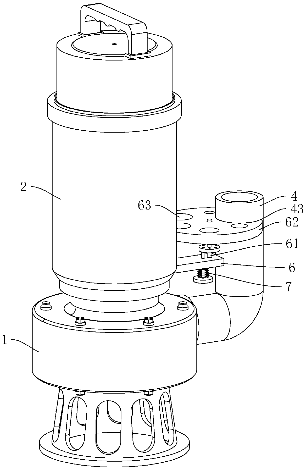
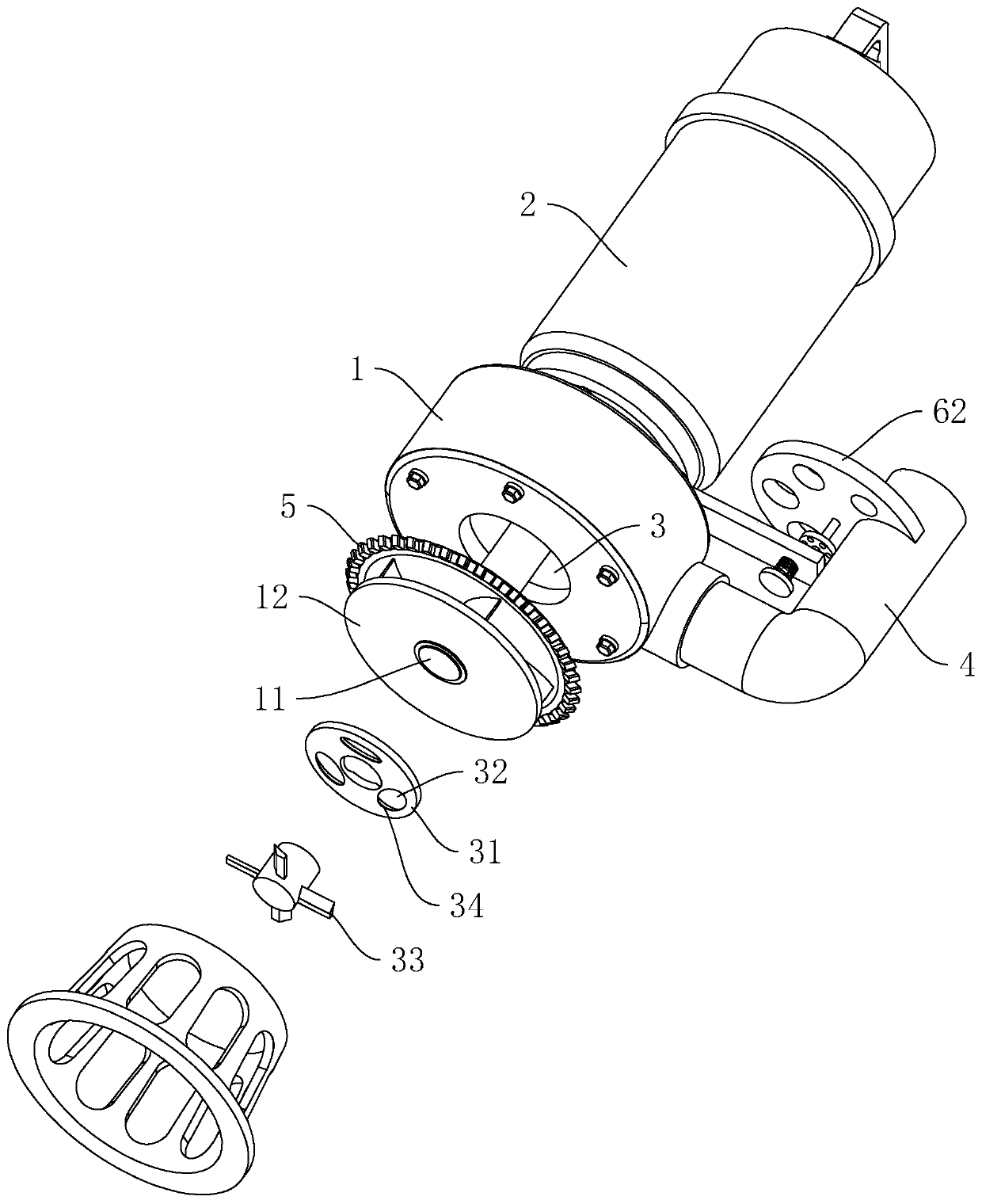
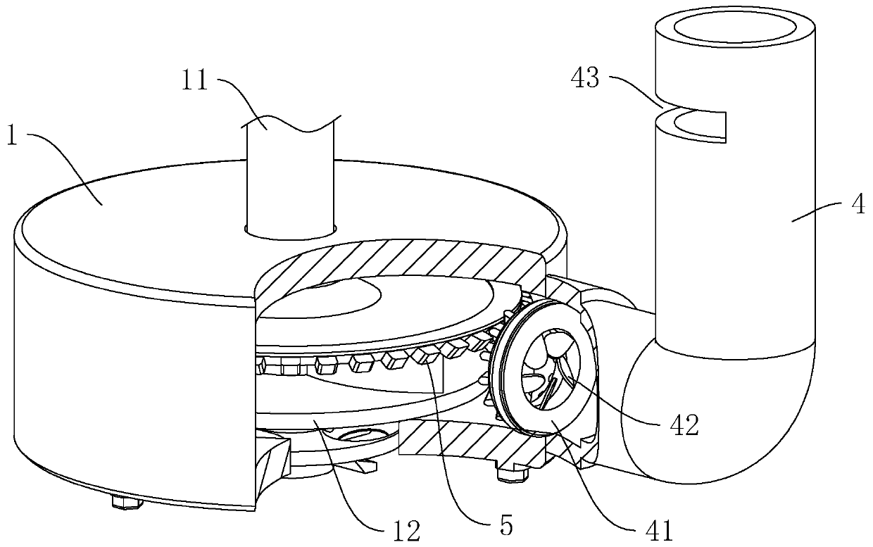
[0036] Embodiment 1: as figure 1 , figure 2 As shown, a submersible pump includes a pump body 1 and a motor 2. A pump shaft 11 is connected to the pump body 1 for vertical rotation. The pump shaft 11 is provided with an impeller 12 located in the pump body 1. The lower end surface of the pump body 1 A water inlet 3 is provided, and a drainpipe 4 connected to the inside is arranged on the side wall bent upward.

[0037] When the above-mentioned submersible pump is in use, the motor 2 is used to drive the pump shaft 11 to rotate. At this time, the pump shaft 11 drives the impeller 12 to rotate synchronously, and the water flow is sucked into the pump body 1 along the water inlet 3, and then the water flow is drawn along the drain pipe. 4 discharge, realize the suction and discharge of water flow.

[0038] like figure 2 As shown, a cutting disc 31 is horizontally arranged in the water inlet 3 , and a plurality of water inlet holes 32 run through the cutting disc 31 . A cutt...

Embodiment 2

[0053] Embodiment 2: as Figure 5 As shown, a submersible pump differs from Embodiment 1 in that a mounting ring 44 is provided on the outer wall of the upper end of the drain pipe 4, and a mounting sleeve 45 is provided on the upper end surface of the mounting ring 44, and the outer wall of the drain pipe 4 and the mounting sleeve 45 An installation gap 46 is formed between the inner walls, and a viewing hole 451 communicating with the installation gap 46 runs through the outer wall at the lower end of the installation sleeve 45 .

[0054] like Figure 5 As shown, the outer wall of the upper end of the drain pipe 4 is provided with a multi-ring ring gear 47, and the multi-ring ring gear 47 is located inside the installation sleeve 45. uniformly distributed in the axial direction.

[0055] When it is necessary to install the water pipe on the drain pipe 4, first set the water pipe on the outer wall of the drain pipe 4, and then drive the water pipe to move downward. down ex...


PUM


Abstract

The invention discloses a sinking pump, and relates to the field of water pumps. The pump comprises a pump body, and a water draining pipe arranged on the pump body, a supporting base is arranged on the side wall of the pump body, the upper end face of the supporting base is vertically and rotatably connected with a rotating shaft, the supporting base is provided with a locking part for fixing therotating shaft, the upper end of the rotating shaft is horizontally provided with a ring switch plate, a through hole allowing the switch plate to slide is formed in the water draining pipe, multipledifferent specifications of connecting holes are formed in the switch plate, and the connecting holes are evenly distributed in the circumferential direction of the switch plate, and are used for communicating with the water draining pipe. The sinking pump has the following advantages that through setting of the connecting holes with the different hole diameters, communication with the water draining pipe is achieved, the aim that during water flow circulation, the cross section area is adjusted is achieved, the water pressure of the water flow draining position can be changed, the lift adjusting of the water flow can be achieved, the sinking pump can be matched with different lift needs, and the high-suitability effect is achieved.

Description

technical field [0001] The invention relates to the field of water pumps, in particular to a submersible pump. Background technique [0002] Submersible pump is an important equipment for deep well water extraction. When in use, the whole unit is submerged in water to extract groundwater to the surface. It is an indispensable equipment for domestic water, mine rescue, industrial cooling, farmland irrigation, seawater lifting, and ship adjustment. [0003] When the traditional submersible pump is in use, the head at the position of the drain pipe usually remains unchanged, so the head at the position of the drain pipe cannot be adjusted according to different usage requirements, and the adaptability is low, which needs to be improved. Contents of the invention [0004] The object of the present invention is to provide a submersible pump with a high adaptability effect. [0005] The technical purpose of the present invention is achieved through the following technical solut...

Claims


Application Information

Patent Timeline
IPC IPC(8): F04D29/42F04D15/00F04D29/00F04D29/62F04D13/08F04D13/10
CPCF04D13/086F04D13/10F04D15/00F04D29/007F04D29/426F04D29/4293F04D29/628
Inventor 孙仙友陈平
Owner LVMEI PUMP CO LTD
Why Eureka
Try Eureka