a circuit breaker
A circuit breaker and housing technology, applied in the field of circuit breakers, can solve the problems of insufficient safety of circuit breakers
- Summary
- Abstract
- Description
- Claims
- Application Information
AI Technical Summary
Problems solved by technology
Method used
Image
Examples
Embodiment 1
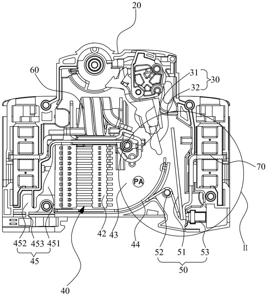
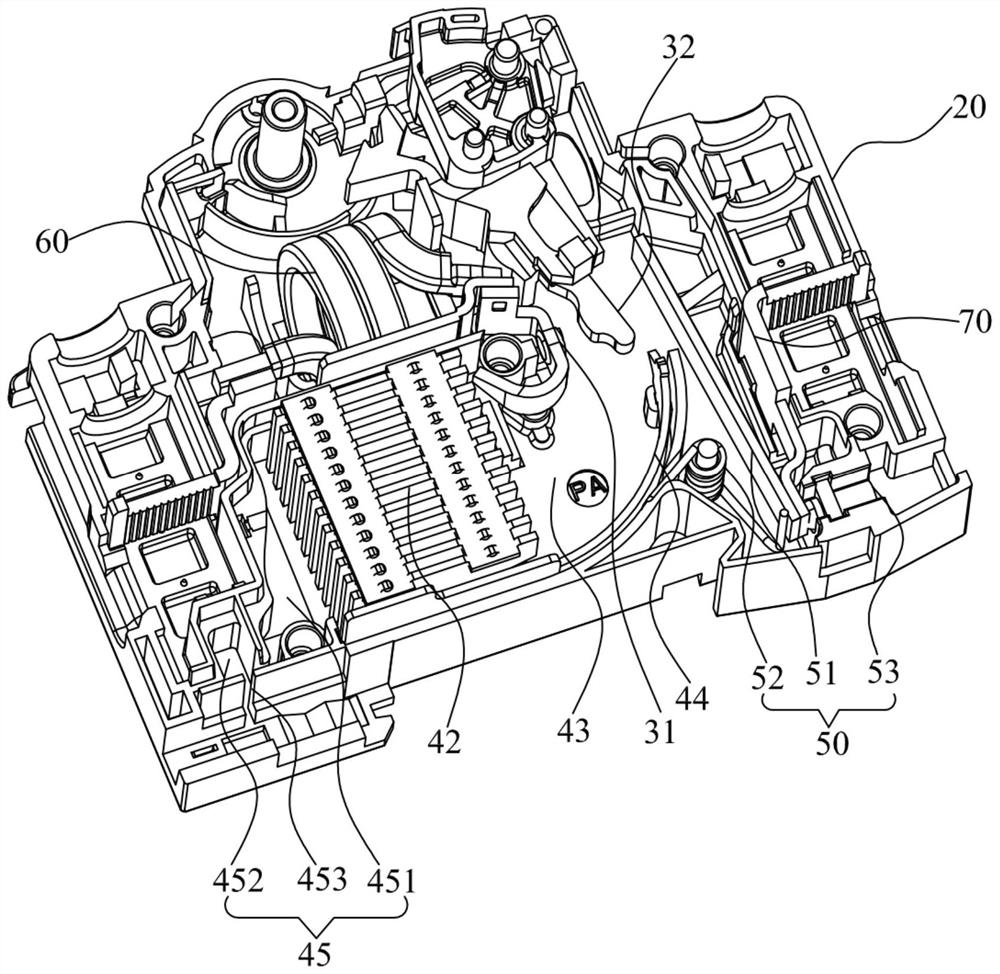
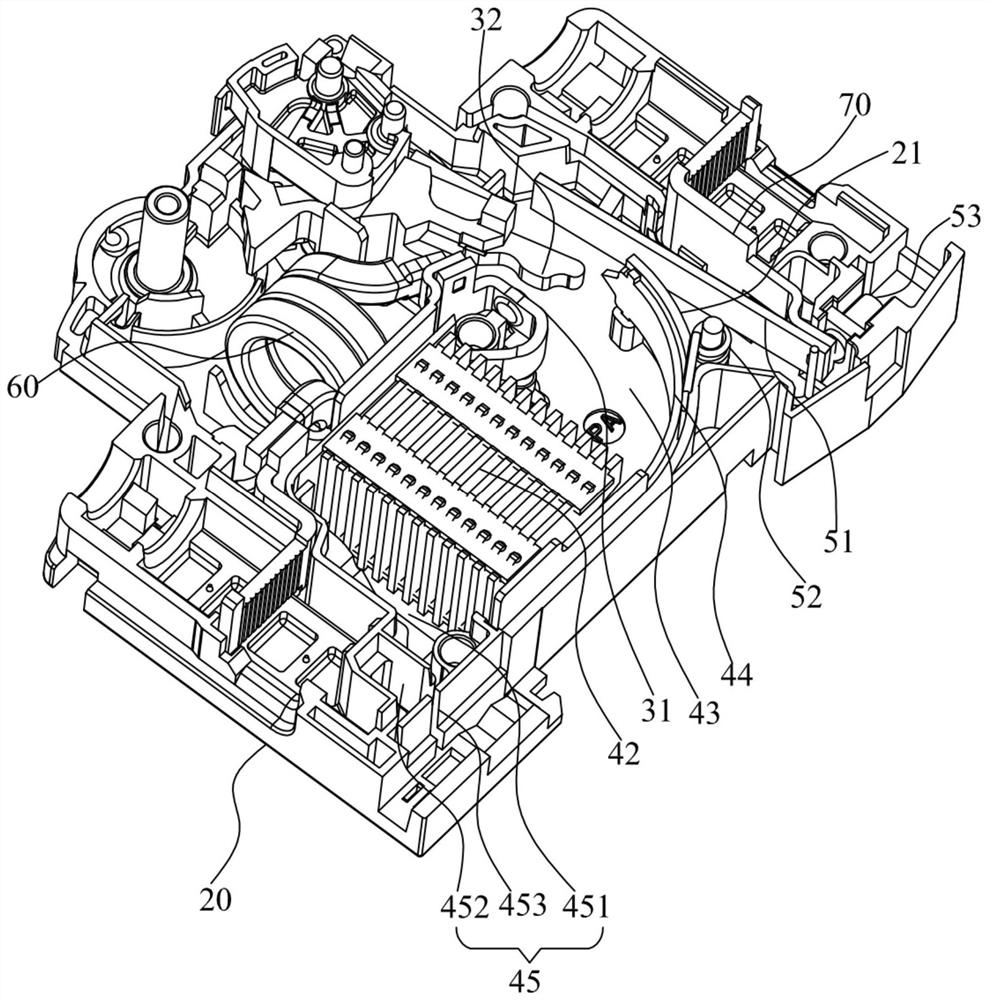
[0029] Such as Figure 1 to Figure 10 Shown is a schematic structural diagram of the circuit breaker provided by the embodiment of the present invention.
[0030] Please check Figure 1 to Figure 10 The circuit breaker provided by the present invention includes a housing 20, an operating mechanism 30 disposed in the housing 20, an arc extinguishing mechanism 40, and an overload protection mechanism 50, wherein the operating mechanism 30 includes a static The contact 31, and the moving contact 32 that is movably arranged in the housing 20 corresponding to the static contact 31; the arc extinguishing mechanism 40 includes an arc extinguishing chamber 41, and an arc extinguishing grid set in the arc extinguishing chamber 41 Group 42, running arc 43, and the arc strike plate 44 that is a tip near the end of the moving contact 32; the overload protection mechanism 50 includes a bimetal 51 that is matched with the moving contact 32 at one end, and is connected with the bimetal 51 a...
Embodiment 2
[0041] Such as Figure 1 to Figure 10 As shown, this embodiment is a more preferred embodiment on the basis of Embodiment 1. In this embodiment, its overload protection mechanism 50 also includes an adjustment screw 53, wherein the adjustment screw 53 is located between the bimetal 51 and the terminal 70 is connected to the housing 20 at one end, and the adjusting screw 53 is located on the side of the bimetal 51 away from the torsion spring 521. At this time, the two sides of the bimetal 51 are connected with the torsion spring 521 and the adjusting screw 53 respectively. Control the screwing in and out of the adjusting screw 53 on one side of the bimetal 51, so that the position of the bimetal 51 can be adjusted, and at the same time, the torsion spring 521 is arranged on the other side of the bimetal 51, so that after thermal adjustment The pressure provided by the torsion spring 521 of the bimetal 51 can always keep the same position, avoiding instability after long-term u...
Embodiment 3
[0050] Such as Figure 1 to Figure 10 As shown, this embodiment is a more preferred embodiment based on the second embodiment. In this embodiment, the side of the arc extinguishing grid group 42 away from the arc runway 43 is provided with an exhaust channel 45, wherein the exhaust The channel 45 includes a first exhaust chamber 451 that communicates with the arc extinguishing chamber 41, a second exhaust chamber 452 connected to the end of the first exhaust chamber 451 away from the arc extinguishing chamber 41, and a second exhaust chamber 452 that passes through the shell. The exhaust port 453 on the side wall of the body 20, wherein the first exhaust chamber 451 and the second exhaust chamber 452 are separated by a partition plate, and the exhaust port 453 is a through hole provided on the side wall of the housing 20, And the exhaust port 453 is set on the side facing the second exhaust chamber 452, wherein, after the arc extinguishing grid group 42 in the arc extinguishin...
PUM
 Abstract
Description
Claims
Application Information
 - Generate Ideas
- Intellectual Property
- Life Sciences
- Materials
- Tech Scout
- Unparalleled Data Quality
- Higher Quality Content
- 60% Fewer Hallucinations
Browse by: Latest US Patents, China's latest patents, Technical Efficacy Thesaurus, Application Domain, Technology Topic, Popular Technical Reports.
© 2025 PatSnap. All rights reserved.Legal|Privacy policy|Modern Slavery Act Transparency Statement|Sitemap|About US| Contact US: help@patsnap.com


