Lockable manipulator end executer device capable of realizing constant-force clamping

An end-effector and manipulator technology, applied in manipulators, program-controlled manipulators, chucks, etc., can solve the problems of secondary progressive damage to the operating object, long clamping operation process, complex structure, etc., and achieve high-efficiency and high-reliability picking or packaging. The effect of automatic operation, improved grasping efficiency and flexible movement

Inactive Publication Date: 2019-10-18
HEBEI AGRICULTURAL UNIV.
View PDF7 Cites 5 Cited by
  • Summary
  • Abstract
  • Description
  • Claims
  • Application Information

AI Technical Summary

Problems solved by technology

In response to this requirement, common grasping manipulators generally use sensor feedback force signals to control force positions, which are often complicated in structure and expensive, and are not easy to be widely promoted in the market; at the same time, because the grasping process requires feedback signals for force control, The grasping operation speed is not high, and the grasping operation process is long, which easily causes secondary progressive damage to the operating object

Method used


Image

  • Lockable manipulator end executer device capable of realizing constant-force clamping
  • Lockable manipulator end executer device capable of realizing constant-force clamping

Examples


Embodiment Construction

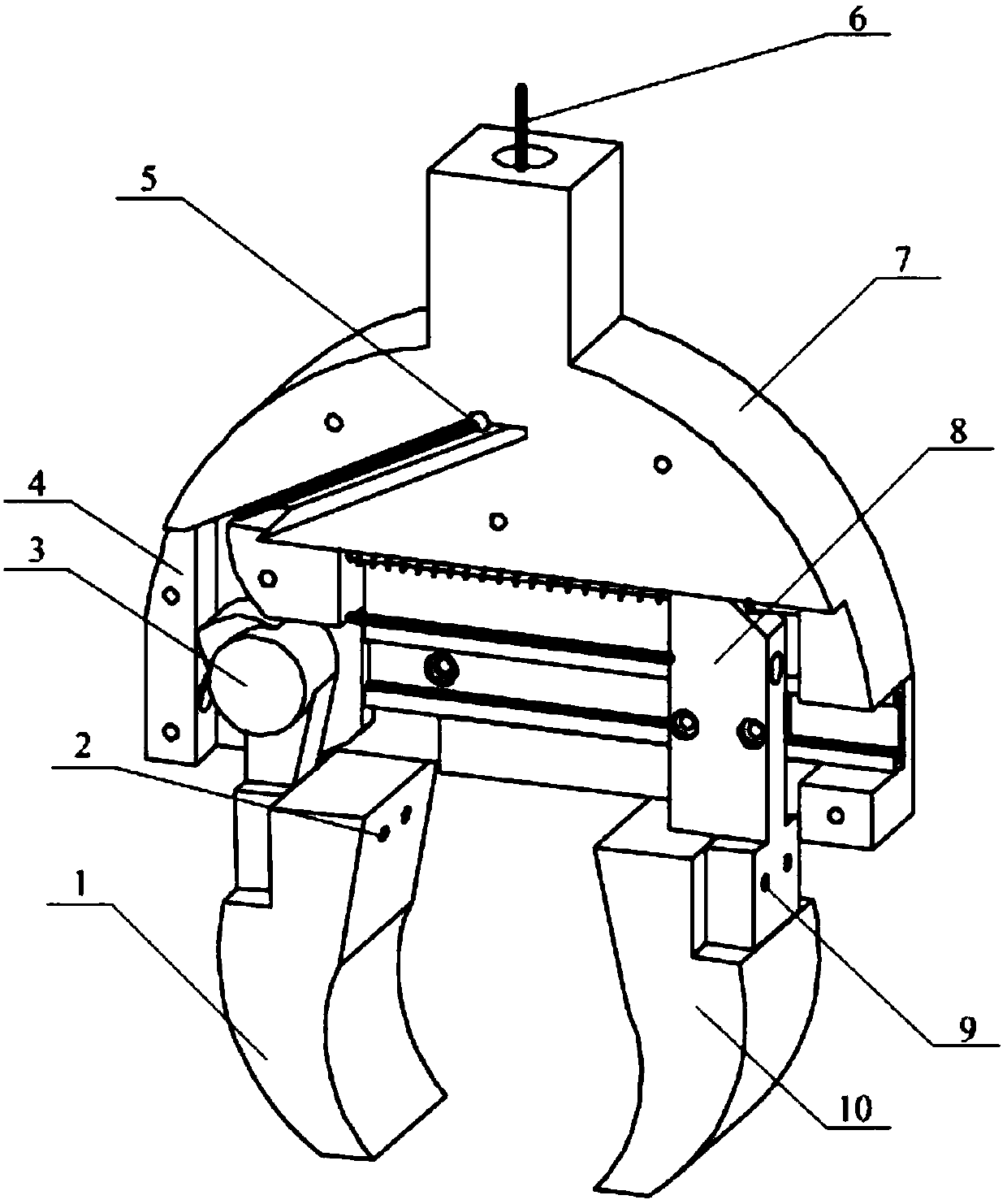
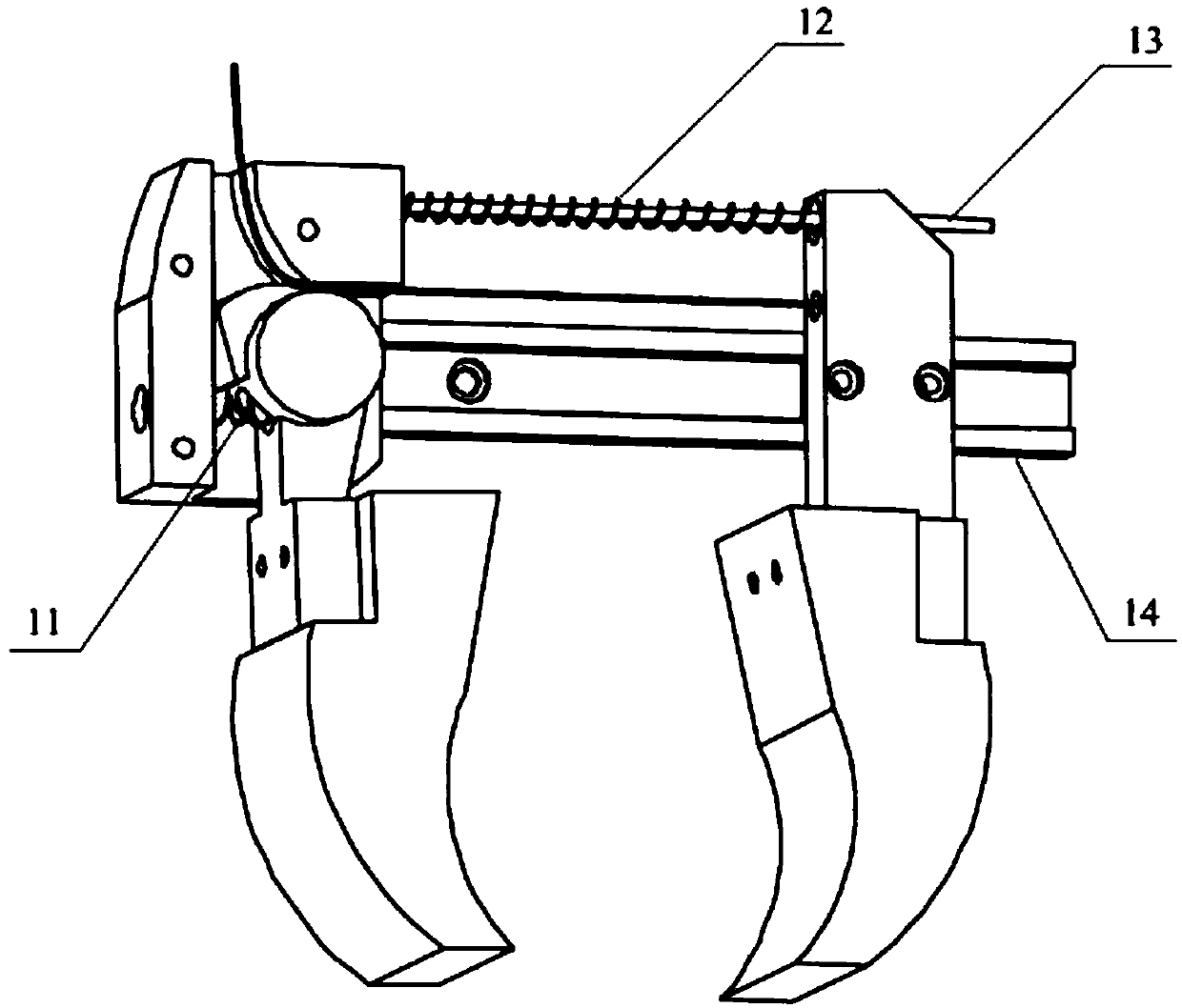
[0008] As shown in Figures 1 and 2, the embodiment of the present invention includes two clamping fingers with different structures: the rotatable finger (1) is connected with one end of the camshaft (3) by a bolt (2), and the camshaft (3) is connected together by a bolt (2). The rotating shaft on one side is connected on the locking member (4), and the pressure spring (11) is connected between the camshaft (3) and the locking member (4), and the locking member (4) is fixed on the frame (7). Slidable finger (10) is connected with slide block (8) by bolt (9), and slide block (8) can slide back and forth on guide rail (14), and guide rail (14) is fixed on the frame (7). The sliding guide post (13) passes through the hole at the top of the slider (8), and the two ends are fixedly connected with the camshaft (3) and the frame (7) respectively, and the return spring (12) is sleeved on the surface of the sliding guide post (13) . The device adopts a manual traction rope (6) to draw...


PUM


Abstract

The invention discloses a lockable manipulator end executer device capable of realizing constant-force clamping. The lockable manipulator end executer device capable of realizing constant-force clamping comprises two main structures, that is, two clamping fingers and a constant-force locking mechanism. A rotatable finger is connected with a cam shaft; the other side of the cam shaft is connected with a locking member, and a pressure spring is connected between the cam shaft and the locking member; and the locking member is fixed to a rack. A slidable finger is connected with a guide rail through a slide block, and capable of realizing back and forth movement, and the guide rail is fixed to the rack. The device is manually dragged through a traction rope; and one side of the traction rope is connected with the slide block through the fit clearance of the cam shaft and an arc-shaped rail on the locking member. The rope is pulled to drag the slide block to drive the slidable finger to clamp a target object; after the target object touches the rotatable finger, the rotatable finger overcomes the effect of the pressure spring and drives the cam shaft to rotate, and the cam shaft is matched with the arc-shaped rail on the locking member; and the traction rope is clamped through friction to form the locking mechanism. At this moment, the clamping forces of the two fingers for the target object keep invariable, so that constant-force lossless clamping for an operation object is realized.

Description

technical field [0001] The invention relates to an end effector device, in particular to an end effector device with a constant force clamping manipulator capable of having a lockable mechanism. Background technique [0002] In the process of automatic harvesting or mechanized packaging, clamping damage is often unavoidable for objects that are easily damaged, such as berries, eggs, and glassware. Since the surface crushing force of these operating objects is very small, the requirements for force control during the clamping process of the manipulator are very strict. At the same time, the gripping action time should be strictly controlled to avoid secondary progressive damage caused by too long action time. For example, for strawberries, the grasping force of the mechanical fingers on the surface of the fruit should not be greater than 1.5N / cm 2 , no more than 3 seconds; for ripe pears, the surface force does not exceed 2.8N / cm 2 , the action time does not exceed 5 secon...

Claims


Application Information

Patent Timeline
Patent Type & Authority Applications(China)
IPC IPC(8): B25J15/08B25J15/00B25J9/10
CPCB25J15/083B25J15/00B25J9/104
Inventor 李娜姜海勇徐宏发赵起超赵子桂赵磊高松岩
Owner HEBEI AGRICULTURAL UNIV.
Why Eureka
Try Eureka