
Modular bridge expansion joint with horizontal swing supporting cross beams

A technology for supporting beams and expansion joints, which is applied in the field of bridge expansion joints, can solve problems such as difficult installation, shortened service life of bridges, and inflexible use, so as to improve shock absorption and isolation performance, alleviate multi-angle impacts, and save manpower and material resources Effect

Pending Publication Date: 2019-10-15
HENGSHUI ZHONGTIEJIAN ENG RUBBER +1
View PDF0 Cites 9 Cited by
  • Summary
  • Abstract
  • Description
  • Claims
  • Application Information

AI Technical Summary

Problems solved by technology

Affected by its structural characteristics, the grid-type telescopic device has many limitations: First, the one-to-one structural relationship between the middle beam and the support beam of the telescopic device means that the larger the displacement, the more support that needs to be installed in each support box The more beams, the larger the volume of the support box, and the manufacturing cost will increase significantly
Second, due to relying on the polyurethane control spring to control the displacement, the service life and control ability of the polyurethane will be limited. Generally, the maximum design displacement does not exceed 400mm; The cycle is long, the installation is difficult, and the use is not flexible enough; Fourth, the structure can only realize the expansion and contraction along the bridge direction, and the deflection deformation of the beam is constrained, which cannot meet the large displacement of the transverse bridge direction, the large slope along the bridge direction and the realization of The 3D rotation at the end of the bridge, the multi-angle change of the load caused the damage of the bridge structure to be very prominent, and the frequency of maintenance and replacement increased, which brought safety hazards and social and economic losses to the bridge operation; fifth, one of the middle beams or supporting beams of the telescopic device was damaged, Difficult to replace, high settings cannot be replaced, resulting in the scrapping of the overall structure, high maintenance costs, and shortened service life of the bridge

Method used


Image

  • Modular bridge expansion joint with horizontal swing supporting cross beams
  • Modular bridge expansion joint with horizontal swing supporting cross beams
  • Modular bridge expansion joint with horizontal swing supporting cross beams

Examples


Embodiment Construction

[0024] The structure and working principle of a modular bridge expansion joint provided by the present invention with swing support beams will be further described in detail below with reference to the accompanying drawings.

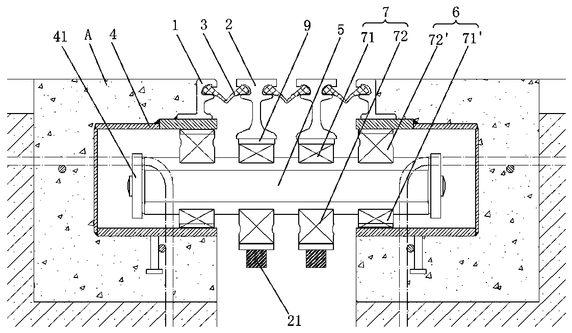
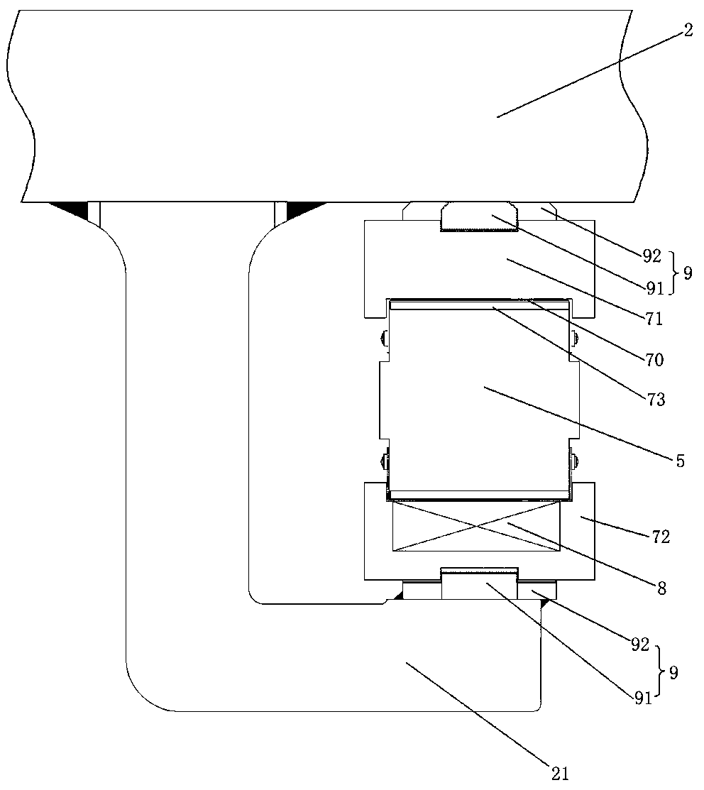
[0025] see figure 1 , is a structural schematic diagram of a modular bridge expansion joint provided by the present invention with a swing support beam. The modular bridge expansion joints with swinging support beams comprise a pair of side beams 1 and at least one middle beam 2 arranged between the side beams 1, the side beam 1 and the middle beam 2 and the adjacent middle beam 2 A waterstop 3 is set between them, and a displacement control box 4 is set at the lower part of the side beam 1. The displacement control box 4 is used to place the end of the support beam 5. The support beam 5 has an oblique angle to the axis of the expansion joint, and the end of the support beam 5 The upper part is defined in the displacement control box 4 by the first swin...


PUM


Abstract

The invention belongs to the technical field of bridge expansion joints, and particularly relates to a modular bridge expansion joint with horizontal swing supporting cross beams. The bridge expansionjoint can move in six degrees of freedom. The modular bridge expansion joint comprises a pair of side beams and at least one middle beam arranged between the side beams, water stopping belts are arranged between the side beams and the middle beams and between the adjacent middle beams, a displacement control box is arranged on the lower portions of the side beams, the displacement control box isused for placing the ends of the supporting cross beams, an inclined angle is formed between the supporting cross beams and the axis of the expansion joint, the end parts of the supporting cross beamsare limited in the displacement control box through first horizontal swinging mechanisms, lifting hooks capable of stretching and sliding on the supporting cross beams are arranged at the lower partsof the middle beams, and second horizontal swinging mechanisms for limiting the beam bodies of the cross beams are arranged in the lifting hooks. The novel modular bridge expansion joint has the characteristics that the structure is simple and stable, the novel modular bridge expansion joint is suitable for large displacement movement, transverse stretching, vertical lifting, horizontal swingingand six-degree-of-freedom motion change are realized through the horizontal swing supporting cross beams, and the modular bridge expansion joint is convenient to install and maintain.

Description

technical field [0001] The invention belongs to the technical field of bridge expansion joints, and in particular relates to a modular bridge expansion joint with a swinging support beam, which realizes the movement of the bridge expansion joint in six degrees of freedom. Background technique [0002] Bridge expansion joints are usually set between two girder ends, between the girder end and the abutment, or at the hinged position of the bridge to meet the deformation requirements of the bridge deck. It can freely expand and contract in two directions parallel to and perpendicular to the bridge axis, and the connection is firm and reliable. When the vehicle passes by, it should be smooth, without sudden jumps and noises. [0003] At present, modular bridge expansion joints are widely used and the technology is the most mature, especially suitable for bridge structures with large displacement. , the total displacement of the telescopic device is divided into N telescopic mod...

Claims


Application Information

Patent Timeline
Patent Type & Authority Applications(China)
IPC IPC(8): E01D19/06
CPCE01D19/06E01D19/065
Inventor 武发扬侯若敬李淑明常丰年郭庆军姜建强刘保志
Owner HENGSHUI ZHONGTIEJIAN ENG RUBBER
Learn More