
Ring main unit three-location isolation operation mechanism

An operating mechanism and three-station technology, applied in the direction of contact drive mechanism, air switch parts, switchgear, etc., can solve the problems of large operating force, inconvenient maintenance, long power failure time, etc., and achieve fewer parts and simple structure Reasonable and well-designed effects

Pending Publication Date: 2019-10-11
ASIA ELECTRICAL POWER EQUIP SHENZHEN CO LTD
View PDF0 Cites 2 Cited by
  • Summary
  • Abstract
  • Description
  • Claims
  • Application Information

AI Technical Summary

Problems solved by technology

[0003] The faults of existing isolating switches mostly occur on the operating mechanism. Because there are many parts in the body of the mechanism, the operation is cumbersome, and the isolating opening and closing spring and the grounding opening and closing spring are separately set up. The overall volume is relatively large. Most of the action directions of the main shaft are driven by gears, the operating force is relatively large, and the transmission accuracy is low
On the other hand, most of the operating mechanism is fixed on the ring network cabinet together with the main body of the isolating switch. If the operating mechanism is damaged, the isolating switch will fail, and it needs to be disassembled from the ring network cabinet for processing, resulting in a longer power outage due to maintenance, and Maintenance is very inconvenient

Method used


Image

  • Ring main unit three-location isolation operation mechanism
  • Ring main unit three-location isolation operation mechanism
  • Ring main unit three-location isolation operation mechanism

Examples


Embodiment Construction

[0027] In order to fully understand the technical content of the present invention, the technical solutions of the present invention will be further introduced and illustrated below in conjunction with specific examples, but not limited thereto.

[0028] The following will clearly and completely describe the technical solutions in the embodiments of the present invention with reference to the accompanying drawings in the embodiments of the present invention. Obviously, the described embodiments are only part of the embodiments of the present invention, not all of them. Based on the embodiments of the present invention, all other embodiments obtained by persons of ordinary skill in the art without creative efforts fall within the protection scope of the present invention.

[0029] It should be noted that all directional indications (such as up, down, left, right, front, back, etc.) in the embodiments of the present invention are only used to explain the relative relationship bet...


PUM


Abstract

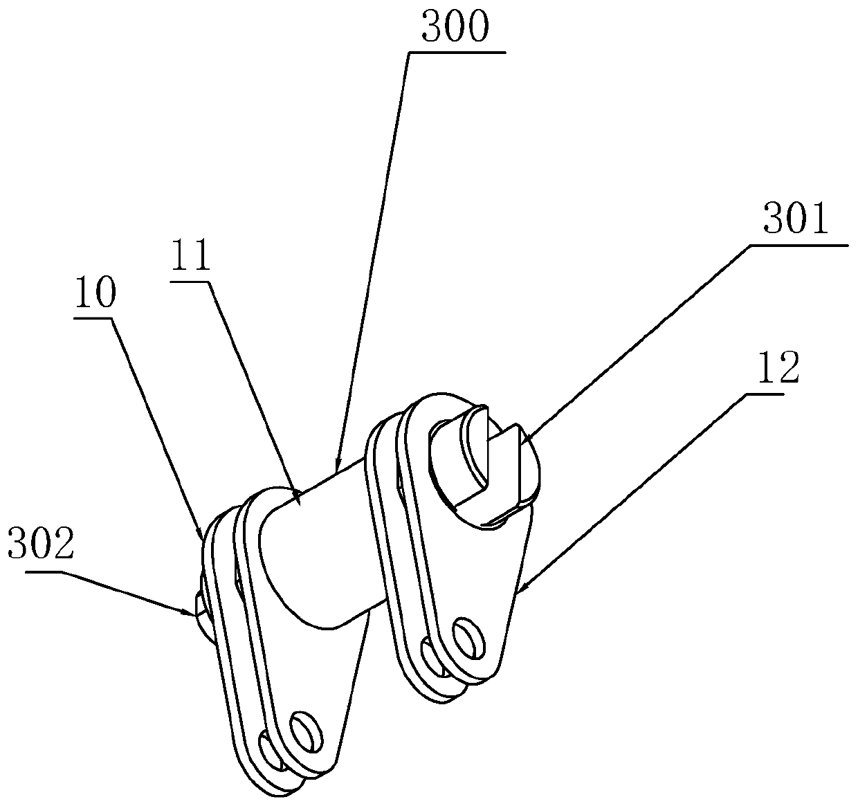
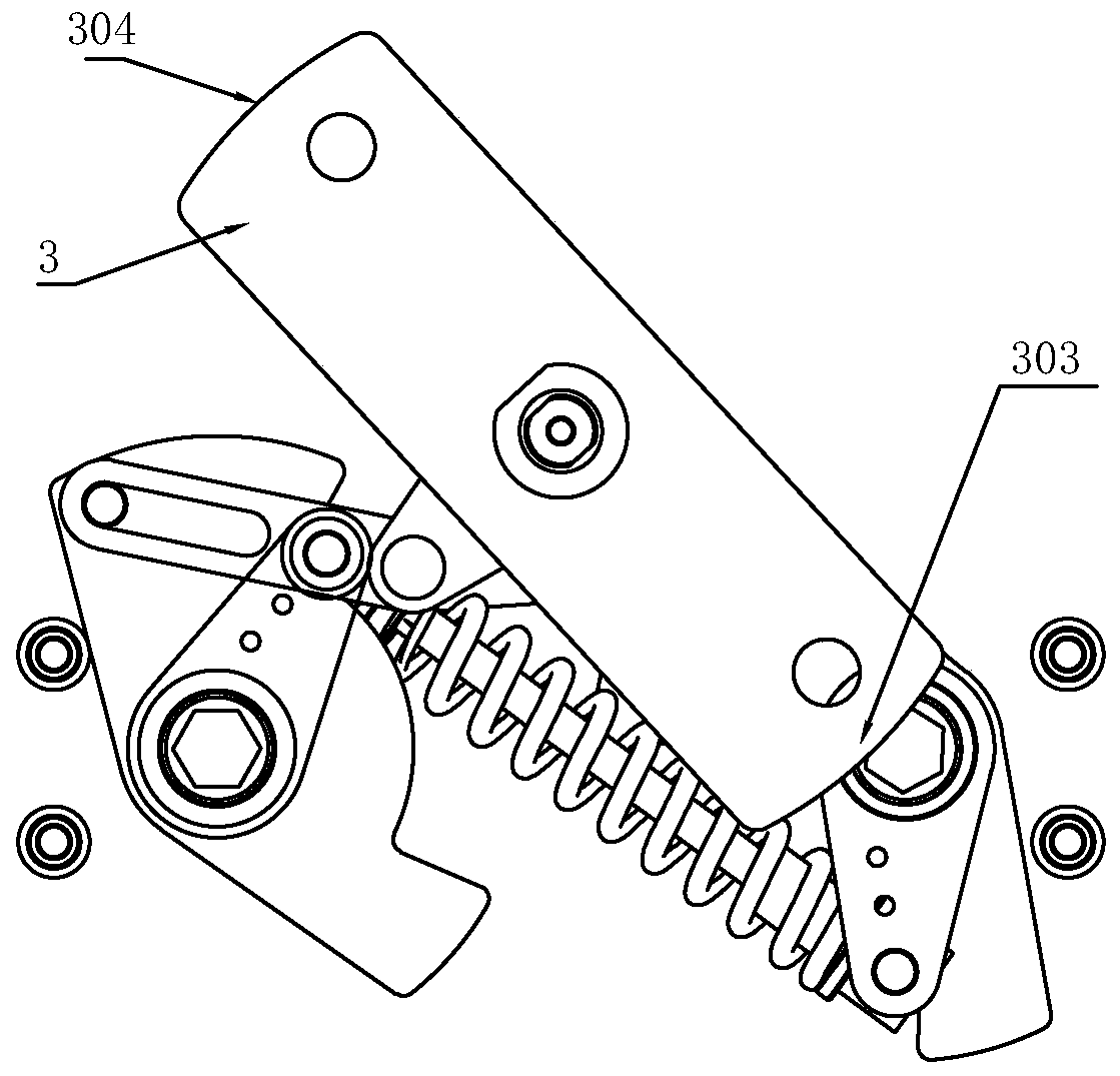
The invention provides a ring main unit three-location isolation operation mechanism. The operation mechanism comprises a front panel, a rear panel, an output shaft module, an energy storage spring module, an isolation operation shaft module, a grounding operation shaft module and an operation hole baffle plate; a holding cavity is arranged between the front panel and the rear panel in parallel; the output shaft module, the isolation operation shaft module and the grounding operation shaft module penetrates through the holding cavity; the isolation operation shaft module an the grounding operation shaft module are arranged at two sides of the output shaft module; the isolation operation shaft module and the grounding operation shaft module are in transmission connection through the outputshaft module; the energy storage spring module is connected between the isolation operation shaft module and the grounding operation shaft module; and the operation hole baffle plate is arranged at the top of the output shaft module. The isolation, the ground switch-on and switch-off processes are accomplished through the spring energy storing release effect, and the performance of the isolationswitch is more stable and reliable.

Description

technical field [0001] The invention relates to the technical field of electrical equipment, and more specifically refers to a three-station isolation operating mechanism of a ring network cabinet. Background technique [0002] At present, with the development of the national economy and the advancement of science and technology, ring network cabinets have been widely used in many large-scale power consumption places; ring network cabinets have simple structure, safe and reliable operation, low maintenance frequency and low operating costs, which are different from traditional ones. Compared with the switch cabinet, the advantages are very prominent. In the technology of the ring network cabinet, isolating switches are widely used. As a circuit switch in the ring network cabinet, the disconnector not only serves as an ordinary switch, but also ensures the reliable grounding of the safety fracture and the lower end of the isolation, which absolutely guarantees the safety of ...

Claims


Application Information

Patent Timeline
IPC IPC(8): H01H31/02H01H31/10H01H3/38H02B13/00
CPCH01H3/38H01H31/02H01H31/10H02B13/00
Inventor 郭予龙高向华杜立春娄清宇
Owner ASIA ELECTRICAL POWER EQUIP SHENZHEN CO LTD
Learn More