Dynamic display board of marketing publicity
A display board and dynamic technology, applied in the field of display boards, can solve the problems that the display boards cannot be dynamically displayed, and achieve the effect of easy disassembly
- Summary
- Abstract
- Description
- Claims
- Application Information
AI Technical Summary
Problems solved by technology
Method used
Image
Examples
specific Embodiment approach 1
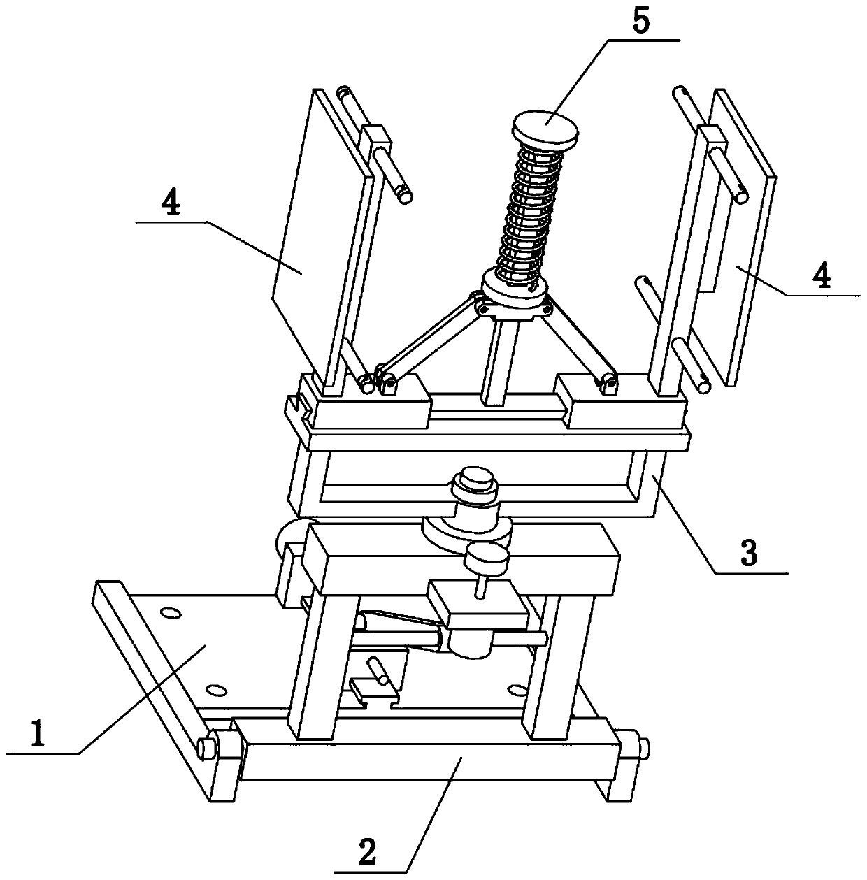
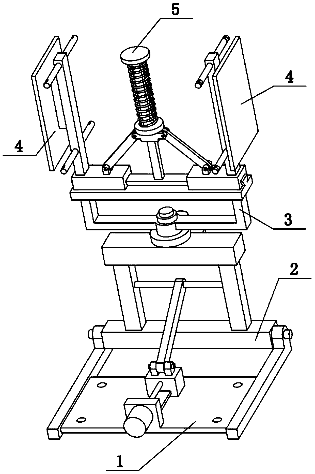
[0029] Combine below Figure 1-10 To illustrate this embodiment, the present invention relates to a display card, more specifically a dynamic display card for marketing promotion, including a base 1, a chassis 2, a circular turntable 3, a display card frame 4 and an elastic mechanism 5. The present invention The base frame 2 can be rotated on the base 1 to adjust the angle of the display card holder 4; the circular turntable 3 can be rotated in a circle on the base frame 2 to realize dynamic display, and the two display card holders 4 are used for hanging Set a soft display card, and the soft display card is easy to disassemble.
[0030] The bottom frame 2 is hingedly connected to the base 1, and the circumferential turntable 3 is rotatably connected to the upper end of the bottom frame 2. There are two display card frames 4 on the left and right, and the two display card frames 4 are respectively slidably connected to the ends of the circumferential turntable 3. At the left ...
specific Embodiment approach 2
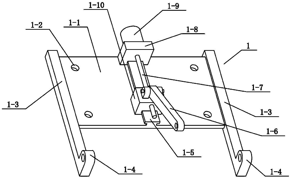
[0032] Combine below Figure 1-10 To illustrate this embodiment, the base 1 includes a bottom plate 1-1, a bottom bar 1-3, a convex seat 1-4, a T-shaped slide rail 1-5, a diagonal bar 1-6, a screw 1-7, and a motor seat I1 -8, motor I1-9 and slide block 1-10, two bottom bars 1-3 are arranged on the left and right sides, the two bottom bars 1-3 are connected through the bottom plate 1-1, and the middle end of the bottom bar 1-1 is fixed T-shaped slide rails 1-5 are connected, slide blocks 1-10 are slidably connected to the T-shaped slide rails 1-5, the upper ends of the slide blocks 1-10 are hingedly connected with inclined rods 1-6, and the rear ends of the base plates 1-1 The motor base I1-8 is fixedly connected, the rear end of the motor base I1-8 is fixedly connected with the motor I1-9, and the front output shaft of the motor I1-9 is fixedly connected with the lead screw 1-7, and the lead screw 1-7 passes through the screw thread Cooperating with the slider 1-10, the front...
specific Embodiment approach 3
[0034] Combine below Figure 1-10To illustrate this embodiment, the underframe 2 includes a lower horizontal column 2-1, an end shaft 2-2, a connecting column 2-3, a circular shaft 2-4, an upper horizontal column 2-5, a central axis 2-6, a limit Bit ring 2-7, gear 2-8, motor seat II2-9 and motor 2-10, the left and right ends of lower cross column 2-1 are all fixedly connected with end shaft 2-2, and two end shafts 2-2 respectively Rotationally connected to the two convex seats 1-4, the left and right ends of the upper end of the lower horizontal column 2-1 are fixedly connected with the connecting column 2-3, and the middle ends of the two connecting columns 2-3 are fixedly connected with a circular shaft 2-4, an upper horizontal column 2-5 is fixedly connected between the upper ends of the two connecting columns 2-3, the upper horizontal column 2-5 is fixedly connected with a motor seat II2-9, and the motor seat II2-9 is fixedly connected with a Motor 2-10, the upper end out...
PUM
 Abstract
Description
Claims
Application Information
 - Generate Ideas
- Intellectual Property
- Life Sciences
- Materials
- Tech Scout
- Unparalleled Data Quality
- Higher Quality Content
- 60% Fewer Hallucinations
Browse by: Latest US Patents, China's latest patents, Technical Efficacy Thesaurus, Application Domain, Technology Topic, Popular Technical Reports.
© 2025 PatSnap. All rights reserved.Legal|Privacy policy|Modern Slavery Act Transparency Statement|Sitemap|About US| Contact US: help@patsnap.com


