
LED light source module and intelligent lamp cap

A technology of LED light sources and modules, applied in the field of LED lighting, can solve the problems of poor light distribution effect and inability to directly transform, and achieve low cost, meet the needs of outdoor lighting, and easy and precise light distribution

Inactive Publication Date: 2019-10-11
HUZHOU MINGSHUO OPTOELECTRONICS TECH CO LTD +1
View PDF10 Cites 1 Cited by
  • Summary
  • Abstract
  • Description
  • Claims
  • Application Information

AI Technical Summary

Problems solved by technology

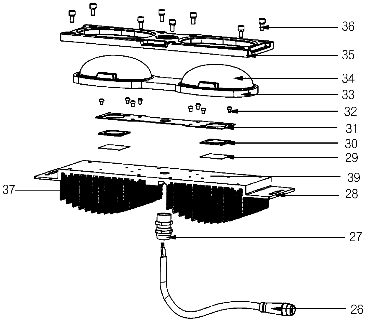
[0010] In order to solve the problem that the transformation of high-pressure sodium lamp street lamps cannot be directly carried out at the present stage, and the problem that the light distribution effect becomes worse due to the addition of a video monitoring device, the present invention provides a brand-new LED light source module and the use of the LED Smart light head for light source module

Method used


Image

  • LED light source module and intelligent lamp cap
  • LED light source module and intelligent lamp cap
  • LED light source module and intelligent lamp cap

Examples


Embodiment 1

[0108] The smart lamp head of this embodiment includes: a first integrated module, the first integrated module includes a first module liner 5 and a camera 3, the first module liner 5 is provided with an opening, and the camera 3 is embedded in the The opening of the first module liner 5; the second integrated module, the second integrated module includes: the second module liner 16 and the intelligent control device 4; the third integrated module, the third integrated module includes: the third module The backing plate 17 and the horn 8; and the LED light source module 9, the lamp housing upper cover 1, the lamp housing base 32, the camera bracket 2, the integrated antenna box 6, the horn installation box 7 and the horn cover 10. When assembling the smart lamp holder, the first integrated module, the second integrated module and the third integrated module are arranged in the lamp housing, and the first module liner 5, the second module liner 16, and the third module liner 17 a...

Embodiment 2

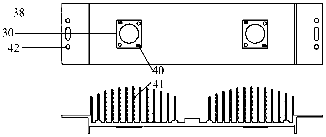
[0113] The only difference between Embodiment 2 and Embodiment 1 is that in the LED light source module 9, the ratio of the shorter length to the longer length of the two adjacent heat dissipation fins 37 is 90% to 92%.

Embodiment 3

[0115] The only difference between Embodiment 3 and Embodiment 1 is that in the LED light source module 9, the ratio of the shorter length to the longer length of the two adjacent heat dissipation fins 37 is 93%-95%.


PUM


Abstract

The invention discloses an LED light source module. The LED light source module comprises a radiator, one or more light source chips, glass lenses with the number being equal to that of the light source chips, a PCB connecting board and a pressing cover, wherein the radiator comprises a heat dissipation base plate and at least one group of heat dissipation fins; the heat dissipation fins are positioned on the same side of the heat dissipation base plate and are vertical to the heat dissipation base plate; each group of heat dissipation fins comprises three or more heat dissipation fins; in each group of heat dissipation fins, the heat dissipation fins are arranged in parallel; in each group of heat dissipation fins, in the direction vertical to the heat dissipation base plate, the lengthsof the different heat dissipation fins are gradually reduced towards two ends from the middle; and the light source chips are connected with the radiator, the PCB connecting board is connected with the light source chips and the radiator, and the glass lenses are fixed on the PCB connecting board. The invention further discloses an intelligent lamp cap comprising the LED light source module. The LED light source module provided by the invention is uniform in heat dissipation, good in heat dissipation effect, little in used material, small in integral weight and size, low in cost, and convenient to replace.

Description

Technical field [0001] The invention relates to the technical field of LED lighting, in particular to an LED light source module and a smart lamp holder using the LED light source module. Background technique [0002] In 2017, the CSA016-2015 "LED Lighting Application and Interface Requirements: Non-integrated LED Module Road Lamps / Tunnel Lamps" standard was developed by the National Semiconductor Lighting Engineering Research and Development and Industry Alliance in 2017. Through the setting of this standard, LED road lighting can be achieved The light source module is standardized, and the products meet the requirements of interchangeability. The light source module that meets the requirements of this standard uses a standardized light source module based on an array of 1W or 3W lamp beads. The advantage of using this light source module is that the light source is scattered and the heat dissipation performance is good, but the defect is The high light difficulty has no small ...

Claims


Application Information

Patent Timeline
Patent Type & Authority Applications(China)
IPC IPC(8): F21S8/00F21V5/04F21V15/01F21V17/16F21V23/04F21V29/76F21V31/00F21V33/00F21Y115/10
CPCF21S8/00F21V5/04F21V15/01F21V17/164F21V23/04F21V31/005F21V33/0052F21V29/76F21Y2115/10Y02B20/72
Inventor 陈威周丽彬
Owner HUZHOU MINGSHUO OPTOELECTRONICS TECH CO LTD
Learn More