
Exhaust steam waste heat circulating system

A circulating system and waste heat technology, applied in the field of exhaust steam preheating circulating system, can solve the problem of not being able to achieve stable regulation of heat supply and stable supply of power generation at the same time, changes in electrical load, and inability to simultaneously ensure heating capacity and power supply capacity, etc. problems, to achieve the effect of reducing operating costs, improving the degree of automation, and ensuring the quality of heating

Pending Publication Date: 2019-10-11
STATE POWER INVESTMENT CORP RES INST
View PDF0 Cites 1 Cited by
  • Summary
  • Abstract
  • Description
  • Claims
  • Application Information

AI Technical Summary

Problems solved by technology

[0003] However, the back-pressure thermoelectric unit in the related art often has the disadvantage that the electrical load changes with the load, that is to say, the back-pressure thermoelectric unit in the related art cannot achieve stable heat supply at the same time under different heat load conditions. The regulation and stable supply of power generation are not convenient for precise regulation under different heat load conditions, especially during the peak heating period, the heating capacity and power supply capacity cannot be guaranteed at the same time

Method used


Image

  • Exhaust steam waste heat circulating system
  • Exhaust steam waste heat circulating system
  • Exhaust steam waste heat circulating system

Examples


Embodiment Construction

[0032] Embodiments of the present invention are described in detail below, examples of which are shown in the drawings, wherein the same or similar reference numerals designate the same or similar elements or elements having the same or similar functions throughout. The embodiments described below by referring to the figures are exemplary only for explaining the present invention and should not be construed as limiting the present invention.

[0033] In describing the present invention, it should be understood that the terms "center", "longitudinal", "transverse", "length", "width", "thickness", "upper", "lower", "front", " Back", "Left", "Right", "Vertical", "Horizontal", "Top", "Bottom", "Inner", "Outer", "Clockwise", "Counterclockwise", "Axial", The orientation or positional relationship indicated by "radial", "circumferential", etc. is based on the orientation or positional relationship shown in the drawings, and is only for the convenience of describing the present invent...


PUM


Abstract

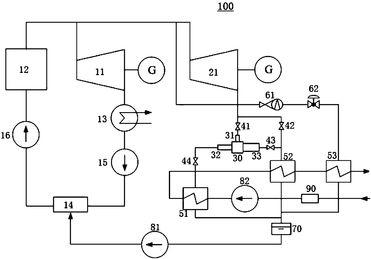
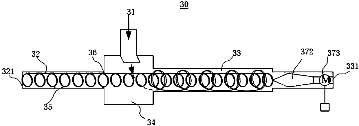
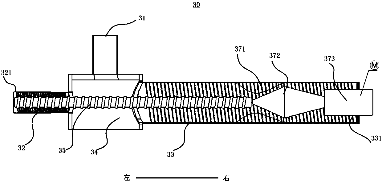
The invention discloses an exhaust steam waste heat circulating system. The exhaust steam waste heat circulating system comprises a condensing type cogeneration unit, a back pressure type cogenerationunit, an energy separation device, a heat supply network unit and a control device, wherein a steam inlet of the back pressure type cogeneration unit is connected with a steam outlet of the condensing type cogeneration unit; the energy separation device is provided with a steam inlet, a cold end outlet and a hot end outlet, and the steam inlet is connected with the steam outlet; a first heat exchanger is connected with the cold end outlet, a second heat exchanger is connected with the hot end outlet and the steam outlet of the back pressure type cogeneration unit, and the first heat exchangerand the second heat exchanger are both connected with the condensing type cogeneration unit; and the control device is configured to control the back pressure type cogeneration unit to switch betweena direct circulation mode and an adjustable heating mode. The exhaust steam waste heat circulating system is simple in structure, can be accurately adjusted under different heat load conditions, andachieves stable adjustment of heat supply quantity and stable supply of power supply quantity.

Description

technical field [0001] The invention relates to the technical field of cogeneration of heat and power, and more specifically, to a exhaust steam preheating cycle system. Background technique [0002] In a thermal power plant, the steam (exhausted steam) heat discharged from the steam turbine is used to supply heat to the heat user, and the production process of simultaneously producing electric energy and heat energy in the same power equipment and circulation system is the cogeneration process of heat and power. The energy-saving and environmental protection benefits of combined heat and power generation are very significant. The condensation heat of exhaust steam discharged into the air-cooling tower or wet-cooling tower accounts for 35%-55% of the total energy of the power plant. The utilization of residual heat is of great significance for the energy-saving transformation of power plants. Compared with pure condensing steam units, combined heat and power generation can s...

Claims


Application Information

Patent Timeline
Patent Type & Authority Applications(China)
IPC IPC(8): F01K27/02F24D1/04F24D19/10F22D11/06
CPCF01K27/02F24D1/04F24D19/1003F22D11/06
Inventor 张谨奕王含李晓蒙刘雨佳江小松毛从清
Owner STATE POWER INVESTMENT CORP RES INST
Learn More