Bonding device

A technology of bonding and adhesives, applied in lamination devices, tools for sewing clothes, chemical instruments and methods, etc.

Active Publication Date: 2019-10-11
BROTHER KOGYO KK
View PDF4 Cites 5 Cited by
  • Summary
  • Abstract
  • Description
  • Claims
  • Application Information

AI Technical Summary

Problems solved by technology

Therefore, the cloth end sensor may not be able to detect the end of the cloth with high accuracy.

Method used


Image

  • Bonding device
  • Bonding device
  • Bonding device

Examples


Embodiment Construction

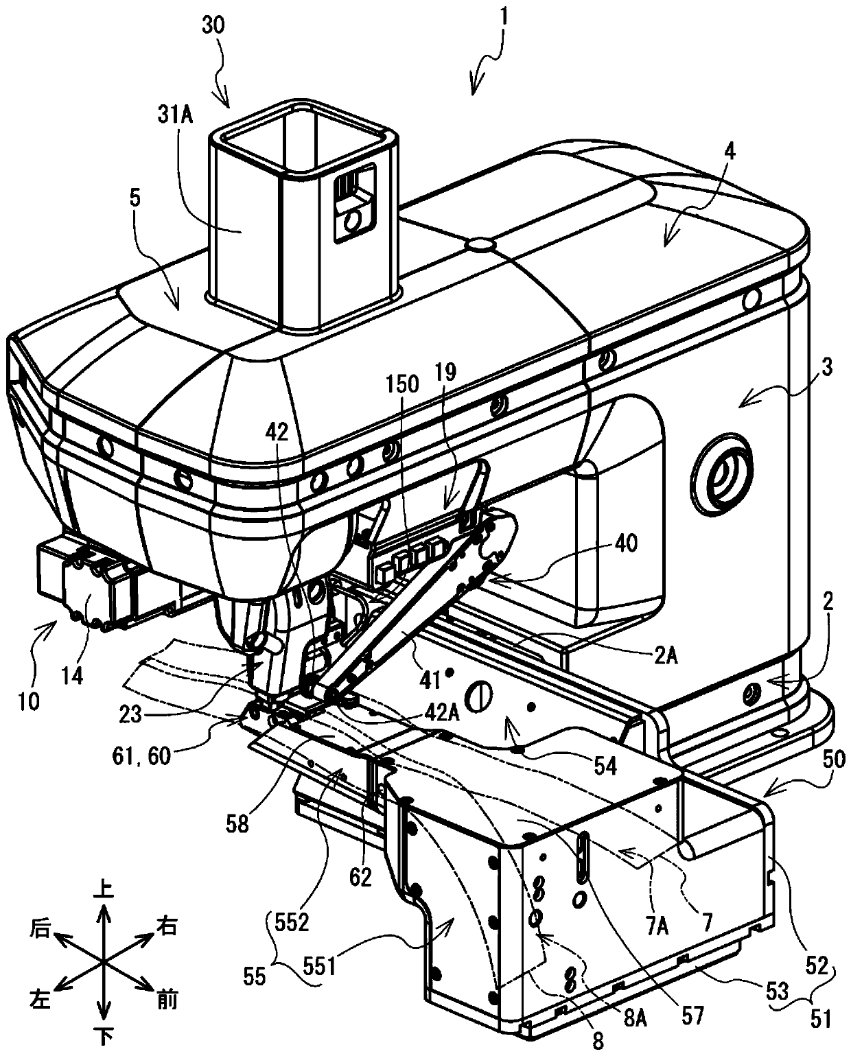
[0035] One embodiment of the present invention will be described. The following description uses left and right, front and rear, and up and down indicated by arrows in the figure. figure 1 The cloth bonding device 1 uses an adhesive to bond two sheets together. The two sheets are, for example, upper cloth 7 and lower cloth 8 . The upper cloth 7 overlaps the lower cloth 8 from above. The cloth bonding device 1 bonds the left end of the upper cloth 7 , that is, the upper specific end 7A, and the right end of the lower cloth 8 , that is, the lower specific end 8A, while feeding the upper cloth 7 and the lower cloth 8 backward. The rear is the downstream side in the conveying direction. The front is the upstream side in the conveying direction.

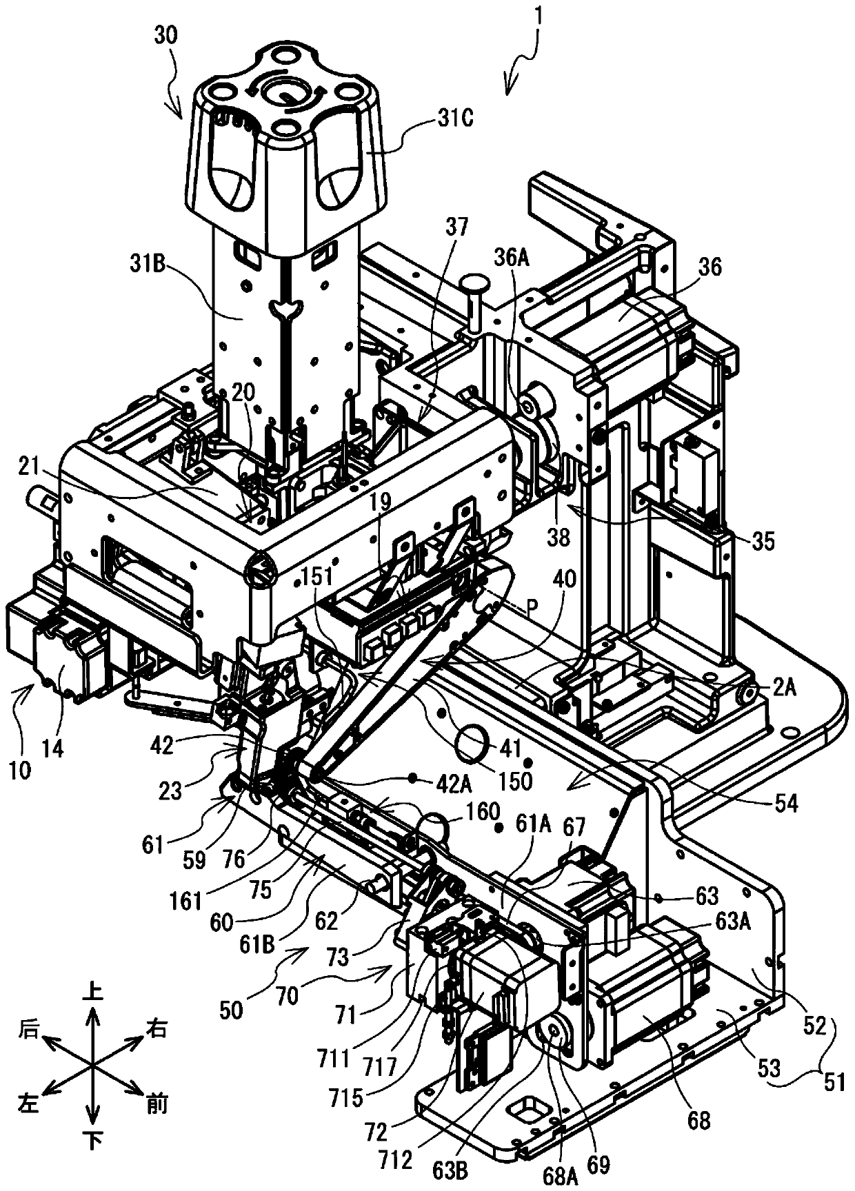
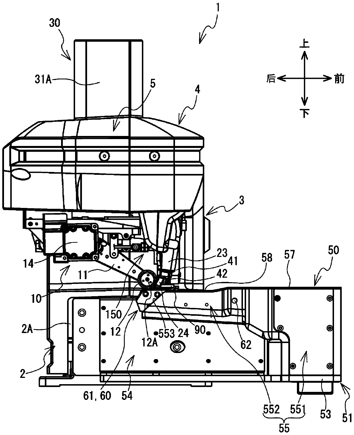
[0036] refer to Figure 1 to Figure 7 The configuration of the cloth bonding apparatus 1 will be described. The cloth bonding apparatus 1 has a base part 2 , a pillar part 3 , an arm part 4 , a head part 5 , and a lower conveying de...


PUM


Abstract

The invention relates to a bonding device capable of ensuring the detection precision of end parts of two sheets when the positions of the two sheets are aligned. When an operator instructs roller movement in order to dispose a fabric to be bonded on a fabric bonding device, a CPU raises an upper conveyance roller to an upper position and performs an ejection process. An upper spraying part and alower spraying part blow air to a reflecting plate arranged on a nozzle and an upper fabric plate, so that chippings or dust can be blown away. When the operator needs to reconfigure the configured lower fabric, a knee control switch is set to be turned on. The CPU adjusts a nozzle gap to a retreat gap and performs injection processing.

Description

technical field [0001] The invention relates to a bonding device. Background technique [0002] The bonding device of Japanese Patent Publication No. 106065 in 2011 discharges adhesive to bond two pieces of cloth to each other. The bonding device has a nozzle, an upper conveying roller, and a lower conveying roller. The nozzle discharges the adhesive downwards. The upper feed roller conveys the lower cloth and the upper cloth while pressing the upper cloth and the lower cloth on which the adhesive is applied between the upper feed roller and the lower feed roller. The bonding device has a cloth end sensor and a reflector. The light emitting part of the cloth end sensor emits light to the reflective plate. The reflective plate reflects the light emitted by the cloth end sensor. The light detection part of the cloth end sensor can detect the light reflected by the reflector. The cloth end sensor judges whether there is cloth above the reflector. The bonding device contr...

Claims


Application Information

Patent Timeline
Patent Type & Authority Applications(China)
IPC IPC(8): A41H43/04B32B37/12B32B37/00B32B37/10B32B41/00
CPCA41H43/04B32B37/12B32B37/0046B32B37/10B32B41/00
Inventor 皆川裕一朗柴田到仓桥俊幸
Owner BROTHER KOGYO KK
Why Eureka
Try Eureka