A Boundary Delineation Method for Polluted Areas

A technology of polluted areas and boundaries, applied in the field of environmental rock mass engineering, can solve problems such as the lack of analysis methods for pollution conditions

Active Publication Date: 2020-11-10
CENT SOUTH UNIV
View PDF3 Cites 0 Cited by
  • Summary
  • Abstract
  • Description
  • Claims
  • Application Information

AI Technical Summary

Problems solved by technology

However, in the actual operation process, it is necessary to sample the area to be tested and bring it back to the room for sample testing. Due to the influence of sampling density and spatial variability of pollutants, the pollution status of the sample points cannot fully reflect the actual pollution status in the demarcated grid. , and in the past, in the environment dominated by rock mass, there was a lack of effective pollution analysis methods

Method used


Image

  • A Boundary Delineation Method for Polluted Areas
  • A Boundary Delineation Method for Polluted Areas
  • A Boundary Delineation Method for Polluted Areas

Examples


Embodiment Construction

[0063] The present invention will be further described in detail below in conjunction with the accompanying drawings.

[0064] The invention discloses a method for delineating the boundary of a polluted area, which includes the following steps:

[0065] Step 1. Establish a wave velocity comparison table for storing reference wave velocities of various types of rock masses when polluted and unpolluted;

[0066] The type of rock mass in the detection area can be determined by consulting relevant geological data;

[0067] By sampling the polluted and unpolluted rock mass around the detection area and the same type as the detection area, and measuring the wave velocity of the sampled rock mass, the wave velocity of each type of rock mass in the polluted and unpolluted state can be determined as a reference wave velocity, stored In the wave speed comparison table;

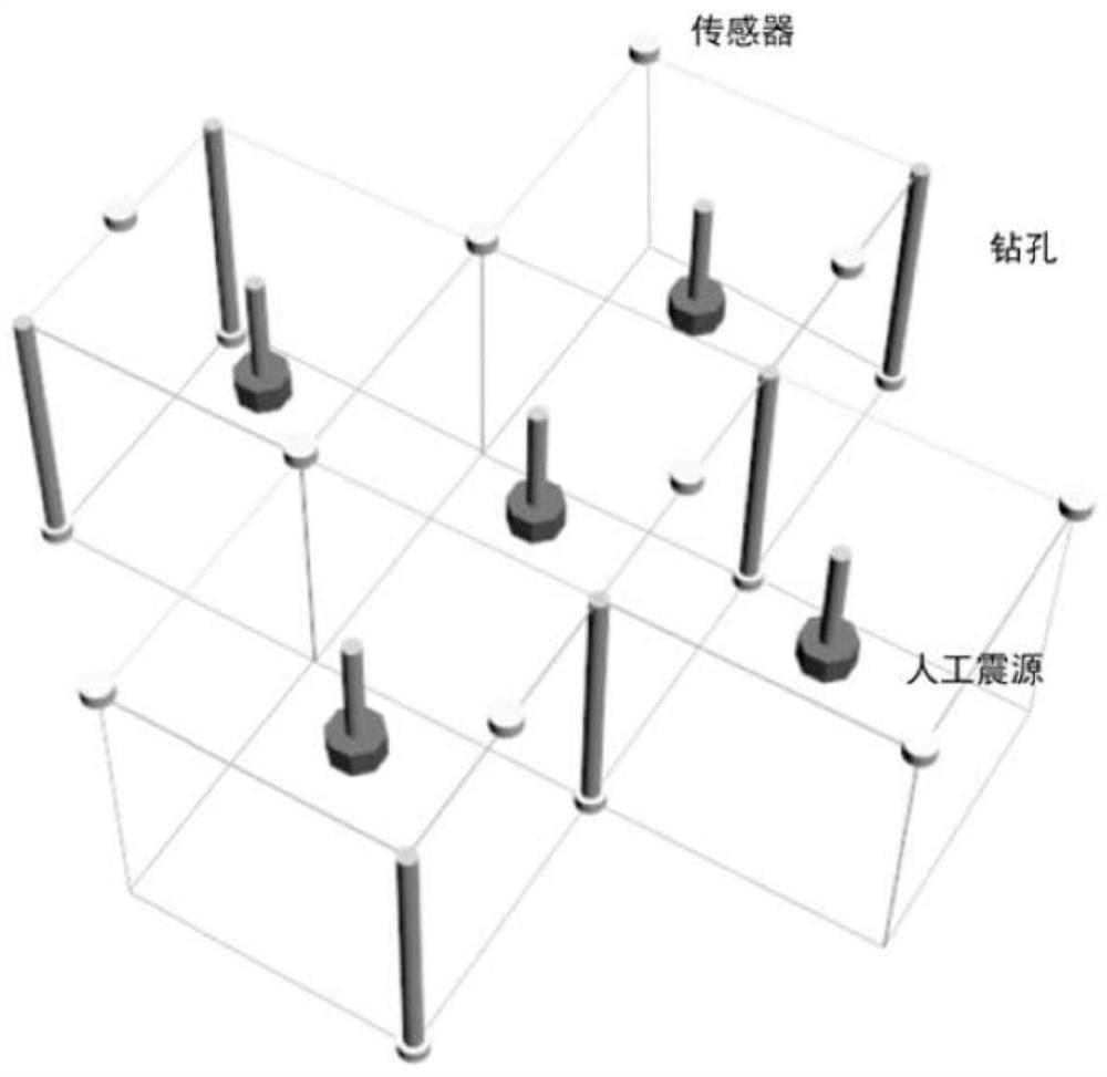
[0068] Step 2, meshing the detection area;

[0069] Divide the detection area into multiple square grids; extend e...


PUM


Abstract

The invention discloses a method for delimiting the boundary of a polluted region. The method comprises the following steps of acquiring the reference wave velocity of various types of rock bodies when not polluted and polluted; carrying out grid division on a detection area, wherein the grid extends to a certain depth in the vertical surface direction to form a grid block; monitoring the rock body wave velocity of the grid blocks; measuring the depth of the polluted grid blocks, and dividing the grid blocks into L layers according to the vertical surface direction, and solving the rock body wave velocity of each sub-layer of the grid block. The pollution range is divided, and if the measured wave velocity of the certain grid block / grid block sub layer is closer to the reference wave velocity of the same type of rock body which is polluted compared to the reference wave velocity of the same type of rock body which is not polluted, the grid block / grid block sub layer is determined intoas a polluted area, and the polluted area is determined according to the peripheries of all the grid block / grid block sub layers. The method disclosed by the invention is based on the wave velocity difference of the rock, the detection area is not required to be sampled and measured, and the pollution range of the detection area can be efficiently and conveniently identified.

Description

technical field [0001] The invention belongs to the technical field of environmental rock mass engineering, and in particular relates to a method for demarcating the boundaries of polluted areas. Background technique [0002] In the development process of mining, petrochemical, textile and other heavy polluting industries, a large amount of pollutants will be produced, among which the discharge of industrial waste water and slag and the accumulation of heavy metal pollutants will cause the pollution of the rock mass environment. In recent years, some "scattered and polluting" enterprises have taken their own interests into consideration, failed to dispose of waste in accordance with relevant national regulations, and directly discharged illegally, resulting in the deterioration of the surrounding rock mass environment, seriously threatening the quality of rock mass engineering and human settlements, causing major hidden dangers to social security. With the increasing awaren...

Claims


Application Information

Patent Timeline
Patent Type & Authority Patents(China)
IPC IPC(8): G01V1/28G01V1/30
CPCG01V1/288G01V1/303G01V1/305G01V2210/6222
Inventor 董陇军张义涵
Owner CENT SOUTH UNIV
Why Eureka
Try Eureka