Self-mounting-dismounting type auxiliary arm mounting mechanism of automobile crane

A technology for a truck crane and an installation mechanism, which is applied to cranes and other directions, can solve the problems of difficult installation, high cost, and difficult implementation, and achieve the effects of high automation, high installation efficiency and simple installation.

Active Publication Date: 2019-10-08
四川长江工程起重机有限责任公司
View PDF7 Cites 2 Cited by
  • Summary
  • Abstract
  • Description
  • Claims
  • Application Information

AI Technical Summary

Problems solved by technology

[0002] At present, medium and small tonnage truck cranes are equipped with jibs during driving and use. After the jib hoisting operation is completed at the workplace, the jib needs to be placed on the side of the main boom and carried on the belt. When the elevation angle of the main boom is -2°, during the installation process, the jib is rotated and installed through the pin shaft hinged with the main jib. When the jib enters the front bracket on the main jib, due to the The gap between the self-weight and the connection between the jib and the pin hole of the main boom causes the height difference between the jib and the rear bracket to be 100-200, which prevents the rear roller group on the jib from entering the rear bracket, and the weight of the jib is about 400-200 900Kg, it is impossible to lift and install the jib by manpower. Only other auxiliary lifting equipment can be used to complete the installation of the jib. Now most of the cases are realized by forklift or another crane. High cost, low efficiency, and often limited by site space, it is difficult to implement and difficult to install

Method used


Image

  • Self-mounting-dismounting type auxiliary arm mounting mechanism of automobile crane
  • Self-mounting-dismounting type auxiliary arm mounting mechanism of automobile crane
  • Self-mounting-dismounting type auxiliary arm mounting mechanism of automobile crane

Examples


Embodiment Construction

[0019] The present invention will be further described below in conjunction with the accompanying drawings and embodiments.

[0020] In order to make the object, technical solution and advantages of the present invention clearer, the present invention will be further described in detail below in conjunction with the accompanying drawings and embodiments. It should be understood that the specific embodiments described here are only used to explain the present invention, not to limit the present invention.

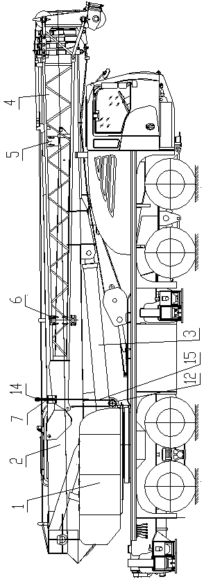
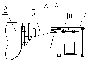
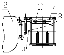
[0021] Such as Figure 1 to Figure 8 As shown, the truck crane self-loading and unloading jib installation mechanism of the present invention includes a turntable 1, a main boom 2, a luffing cylinder 3 connecting the turntable 1 and the main boom 2, and a sub Boom 4, on the same side of the main jib 2 adjacent to the jib, there are fixed a front bracket 5, a rear bracket 6 and a pulley bracket 7, and both the front bracket 5 and the rear bracket 6 are provided with guide co...


PUM


Abstract

The invention discloses a self-mounting-dismounting type auxiliary arm mounting mechanism of an automobile crane. The self-mounting-dismounting type auxiliary arm mounting mechanism comprises a rotarytable, a main boom, an amplitude-variable oil cylinder and an auxiliary arm hinged to the main boom. A front support and a rear support are fixedly arranged on the side, adjacent to the auxiliary arm, of the main boom, and a front roller set and a rear roller set corresponding to the front roller set are arranged on the auxiliary arm. A fixed pulley is fixedly arranged on the rotary table, a pulley frame is fixedly arranged on one side of the main boom, one or more movable pulleys are arranged on the pulley frame, the movable pulley adjacent to the auxiliary arm is higher than the auxiliary arm, one end of a lifting rope is fixedly connected to the main boom, the lifting rope is wound around the fixed pulley and all the movable pulleys, and the other end of the lifting rope is connected with the auxiliary arm. The self-mounting-dismounting type auxiliary arm mounting mechanism has the beneficial effects of being simple in device, low in cost, high in automation degree and high in mounting efficiency, is not limited by field space and is convenient to implement.

Description

technical field [0001] The invention relates to a mounting mechanism for a secondary arm, in particular to a self-loading and dismounting mounting mechanism for a secondary arm of a truck crane. Background technique [0002] At present, medium and small tonnage truck cranes are equipped with jibs during driving and use. After the jib hoisting operation is completed at the workplace, the jib needs to be placed on the side of the main boom and carried on the belt. When the elevation angle of the main boom is -2°, during the installation process, the jib is rotated and installed through the pin shaft hinged with the main jib. When the jib enters the front bracket on the main jib, due to the The gap between the self-weight and the connection between the jib and the pin hole of the main boom causes the height difference between the jib and the rear bracket to be 100-200, which prevents the rear roller group on the jib from entering the rear bracket, and the weight of the jib is a...

Claims


Application Information

Patent Timeline
Patent Type & Authority Applications(China)
IPC IPC(8): B66C23/36B66C23/62B66C23/64B66C23/82
CPCB66C23/36B66C23/62B66C23/64B66C23/821
Inventor 许建春蒋明星邱智黄小章张绍北王强陈建
Owner 四川长江工程起重机有限责任公司
Why Eureka
Try Eureka