Ejection mechanism for inner side of sliding block

A technology of ejector mechanism and slider, which is applied in the field of injection mold design, can solve problems such as mold sticking, increase production cost, damage product appearance, etc., and achieve the effect of ensuring product appearance and saving production cost

Inactive Publication Date: 2019-10-08
KENTA ELECTRONIC MFG KUNSHAN CO LTD
View PDF0 Cites 0 Cited by
  • Summary
  • Abstract
  • Description
  • Claims
  • Application Information

AI Technical Summary

Problems solved by technology

[0002] The traditional slider can only solve the problem of ordinary undercuts. For product structures with complex structures and many undercuts on the same side, such as Image 6 The product 5 shown in the figure, because its sides need to be textured and cannot have any draft angles, after the mold is released, there are no patterns and parting lines on the product. The undercut requires a slider on the side to ensure the high requirements of the above appearance, but because the undercut and all glue positions are formed on the slider, the left side of product 5 is wrapped on the slider as a whole, and the overall friction force increases , when the mold is released, the product will follow the module as a whole, and there will be serious mold sticking. Not only will it not be able to remove the mold, but it will also cause the overall deformation of the side of the product, damage the appearance of the product, and increase the production cost. The traditional ejection structure is only for mold opening. After the product is ejected, it cannot play any role in the problems on the slider

Method used


Image

  • Ejection mechanism for inner side of sliding block
  • Ejection mechanism for inner side of sliding block
  • Ejection mechanism for inner side of sliding block

Examples


Embodiment

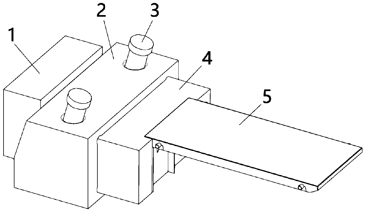
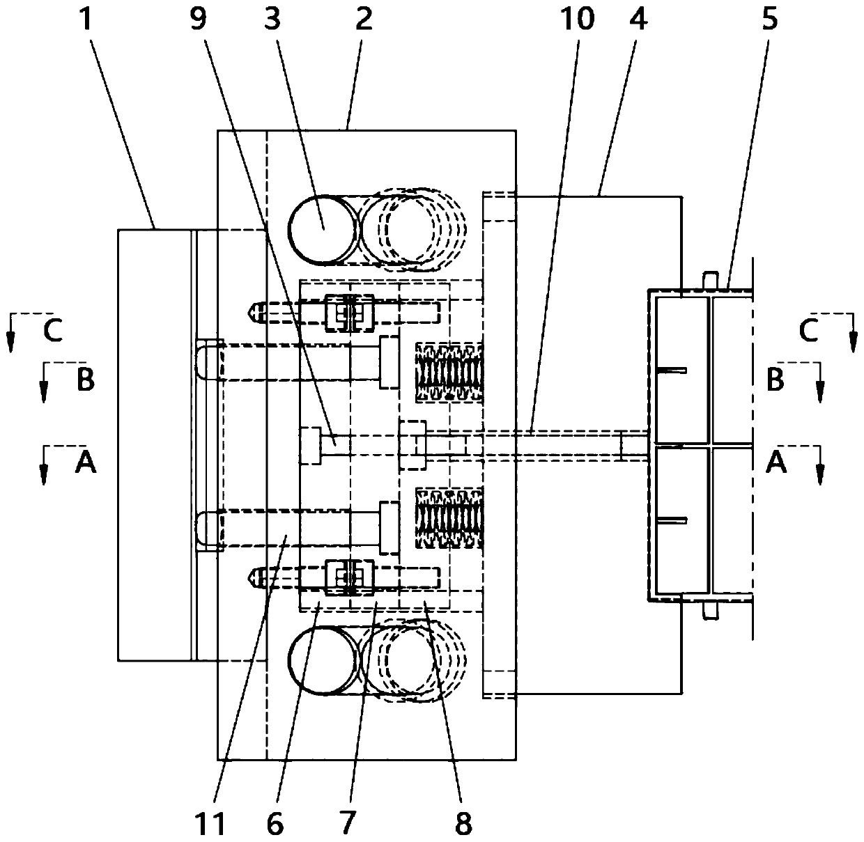
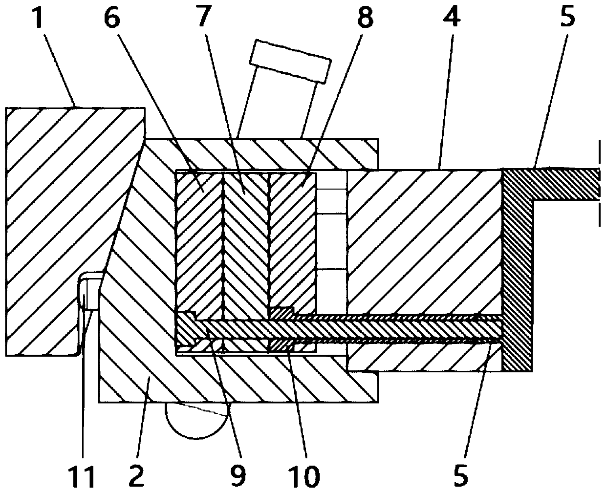
[0017] like Figure 1 to Figure 5 As shown, this embodiment provides a mechanism for ejecting the inner side of the slider, which includes a shovel base 1, a slider seat 2, an oblique guide post 3, and a slider 4; 2 is used to move the slider seat left and right; the upper half of the left side of the slider seat 2 is provided with a first slope, and the right side is fixed with the slider 4; the right side of the shovel base 1 is provided with a The second inclined surface matched with the first inclined surface; the middle position of the lower part of the second inclined surface is provided with a flat position 12; The left fixed block 7, the right fixed block 8 of the tube; the fixed block 6 of the tube needle is fixed with the slider seat 2, and the tube pin 9 which is worn to the right is jointly fixed; the left fixed block 7 of the tube is connected with the The right fixing block 8 of the cylinder is fixed, and is jointly fixed with the cylinder 10 which is penetrated...


PUM


Abstract

The invention relates to an ejection mechanism for the inner side of a sliding block. The ejection mechanism comprises a shovel base, a sliding block seat, inclined guide columns and the sliding block. The inclined guide columns are arranged in the sliding block seat in a penetrating manner and are used for stirring the sliding block seat to move left and right. The left side of the sliding blockseat cooperates with the right side of the shovel base through an inclined face. A level position is arranged at the middle position of the lower portion of an inclined face of the shovel base. An ejector sleeve needle fixing block, an ejector sleeve left fixing block and an ejector sleeve right fixing block are arranged in the sliding block seat. The ejector sleeve needle fixing block and the sliding block seat are fixed, and an ejector sleeve needle arranged rightwards in a penetrating manner is fixed to the ejector sleeve needle fixing block and the sliding block seat. The ejector sleeve left fixing block and the ejector sleeve right fixing block are fixed, and an ejector sleeve which is arranged rightwards in a penetrating manner and arranged on the outer side of the ejector sleeve needle in a sleeving manner and an ejector rod arranged leftwards in a penetrating manner are fixed to the ejector sleeve left fixing block and the ejector sleeve right fixing block. The ejector rod leftwards penetrates through the ejector sleeve needle fixing block and the sliding block seat, and the tail end of the ejector rod is exposed to the outer side of the sliding block seat. According to theejection mechanism for the inner side of the sliding block, the situation that a product is pasted to the sliding block is effectively solved, the product can be subjected to demolding smoothly underthe condition of ensuring that the client requirements are met, the product appearance is guaranteed, and the production cost is saved.

Description

technical field [0001] The invention relates to the field of injection mold design, in particular to a sliding block inner ejection mechanism. Background technique [0002] The traditional slider can only solve the problem of ordinary undercuts. For product structures with complex structures and many undercuts on the same side, such as Image 6 The product 5 shown in the figure, because its sides need to be textured and cannot have any draft angles, after the mold is released, there are no patterns and parting lines on the product. The undercut requires a slider on the side to ensure the high requirements of the above appearance, but because the undercut and all glue positions are formed on the slider, the left side of product 5 is wrapped on the slider as a whole, and the overall friction force increases , when the mold is released, the product will follow the module as a whole, and there will be serious mold sticking. Not only will it not be able to remove the mold, but it...

Claims


Application Information

Patent Timeline
IPC IPC(8): B29C45/44
CPCB29C45/44B29C2045/445
Inventor 蔡峻峰周燕锋黎长发
Owner KENTA ELECTRONIC MFG KUNSHAN CO LTD
Why Eureka
Try Eureka