
Buffer zone configuration method of host memory, storage device and control circuit unit

A storage device and control circuit technology, applied in the direction of instruments, electrical digital data processing, input/output to record carriers, etc., can solve the inconvenience of users, the inability to realize the initialization of the drive memory storage device, and the inability to start the buffer function of the host memory And other issues

Active Publication Date: 2019-10-01
PHISON ELECTRONICS
View PDF9 Cites 2 Cited by
  • Summary
  • Abstract
  • Description
  • Claims
  • Application Information

AI Technical Summary

Problems solved by technology

[0004] In the above process, the host system communicates with the memory storage device through the driver layer, which requires that the driver layer of the host system is compatible with the driver program of the memory storage device, otherwise it is impossible to realize the initialization of the drive memory storage device or to configure the memory storage device with a continuous entity address memory
Then, configuring the host memory buffer through the driver layer requires that the host system has a corresponding driver installed. Therefore, if the user does not install the driver in the host system, the function of the host memory buffer cannot be started, causing the user to the inconvenience

Method used


Image

  • Buffer zone configuration method of host memory, storage device and control circuit unit
  • Buffer zone configuration method of host memory, storage device and control circuit unit
  • Buffer zone configuration method of host memory, storage device and control circuit unit

Examples


Embodiment Construction

[0092] Generally speaking, a memory storage device (also called a memory storage system) includes a rewritable non-volatile memory module and a controller (also called a control circuit unit). Typically memory storage devices are used with a host system so that the host system can write data to or read data from the memory storage device.

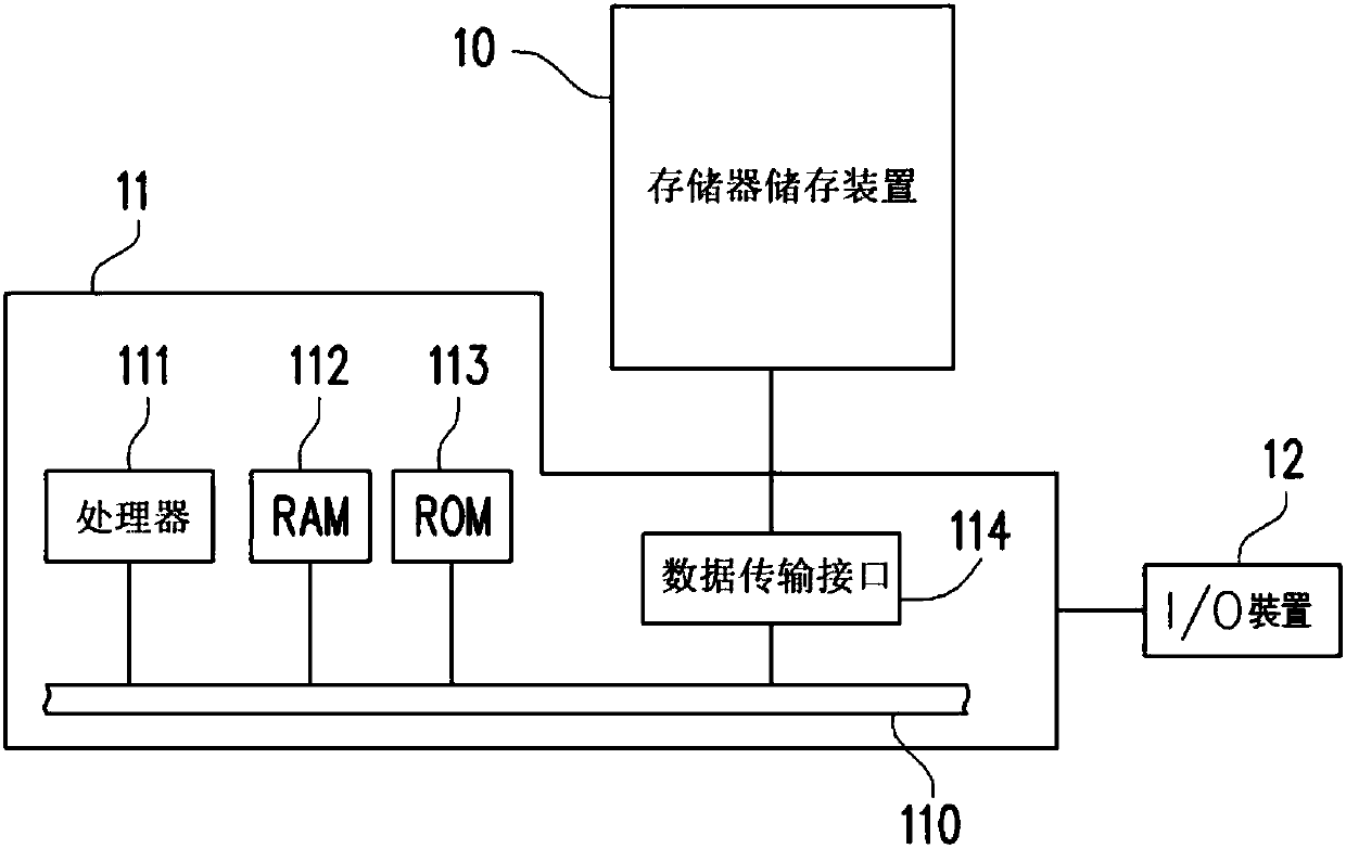
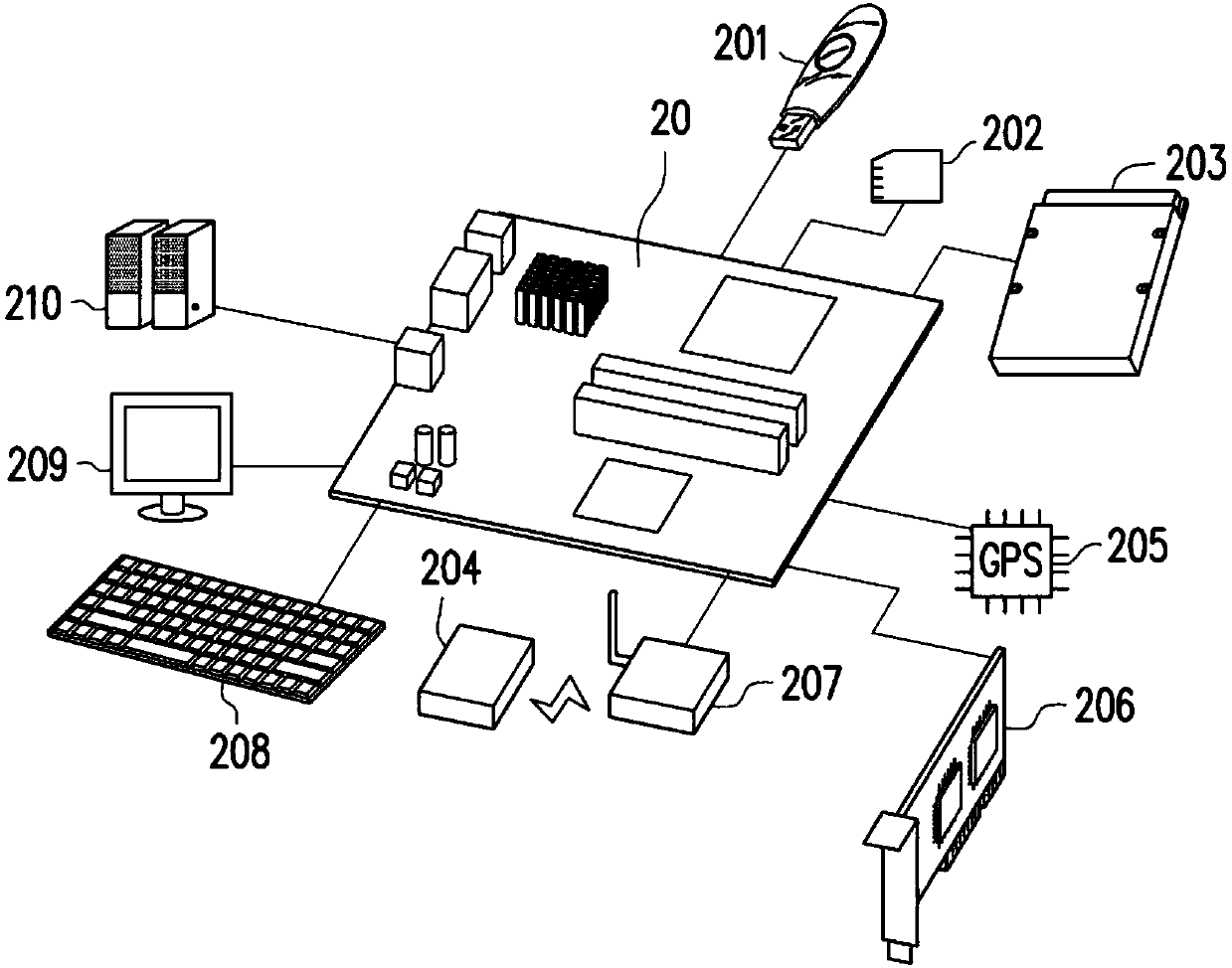
[0093] figure 1 is a schematic diagram of a host system, a memory storage device, and an input / output (I / O) device according to an example embodiment, and figure 2 It is a schematic diagram of a host system, a memory storage device and an input / output (I / O) device according to another exemplary embodiment.

[0094] Please refer to figure 1 and figure 2 , the host system 11 generally includes a processor 111 , a random access memory (random access memory, RAM) 112 , a read only memory (read only memory, ROM) 113 and a data transmission interface 114 . The processor 111 , random access memory 112 , ROM 113 and data transmission interfac...


PUM


Abstract

The invention discloses a buffer zone configuration method of a host memory, a storage device and a control circuit unit. The buffer zone configuration method comprises the following steps: loading aninitialization program of an option read-only memory of a memory storage device into a buffer memory of a host system; an initialization program is executed to configure a continuous entity address in a buffer memory of a host system to a memory storage device as a host memory buffer zone of the memory storage device, and to set and store a flag on the continuous entity address. The buffer zone configuration method further comprises the following steps: when receiving a restart instruction correspondingly pausing to the memory mode, re-establishing a connection with the continuous entity address, and judging whether a mark set on the continuous entity address is the same as the stored mark or not; and if the marks are the same, continuously using the continuous entity address as a host memory buffer zone of the memory storage device.

Description

technical field [0001] The invention relates to a host memory buffer configuration method, a memory storage device and a memory control circuit unit. Background technique [0002] For memory storage devices with different functions, in order to fully utilize the role of the memory storage device in improving the performance of electronic equipment, the current host system has the function of providing a memory buffer (host memory buffer, HMB) for the memory storage device. For example, for an SSD (Solid State Drives) with a storage space of 1TB, the host system, for example, provides a storage space of about 1GB as its host memory buffer. When allocating the host memory buffer, there are generally two opportunities for the host system to drive the host memory buffer, when the driver loads and finds the memory storage device, and when the memory storage device is abnormal or the command triggers a restart during operation. [0003] In order to improve the performance of elec...

Claims


Application Information

Patent Timeline
Patent Type & Authority Applications(China)
IPC IPC(8): G06F3/06
CPCG06F3/0632G06F3/0604G06F3/0656
Inventor 贺孝淇邬正男朱健华
Owner PHISON ELECTRONICS
Learn More