
Down-the-hole drill with cooling function and for mining exploration

A down-the-hole drilling rig, functional technology, applied in the direction of drilling tools, drill pipes, drill pipes, etc., can solve the problems of temperature rise, easy deformation, difficult heat dissipation and cooling, etc., to achieve the effect of improving practicability and prolonging service life

Active Publication Date: 2019-09-27
江门市新会区泰盛石场有限公司
View PDF5 Cites 7 Cited by
  • Summary
  • Abstract
  • Description
  • Claims
  • Application Information

AI Technical Summary

Problems solved by technology

[0003] The surface of existing down-the-hole drilling rigs is generally provided with spiral dimples. When working, the soil around the inner wall of the borehole enters the spiral dimples, and then the drill pipe rotates as the drill pipe leaves the ground, making the spiral dimples The soil is separated from the drill pipe due to the influence of centrifugal force, but some soil is easy to adhere to the drill pipe due to the high humidity, which is not conducive to the complete removal of the soil by the drill pipe. Not only that, when the existing down-the-hole drilling machine is running, the drill When the rod rotates and contacts the subsurface, the temperature is likely to rise sharply due to friction, while the drill rod is drilled into a closed borehole, which is not easy to dissipate heat and cool down, resulting in excessive temperature of the drill rod for a long time, prone to deformation, and shortening the service life of the drill rod , resulting in reduced availability of existing down-the-hole drilling rigs

Method used


Image

  • Down-the-hole drill with cooling function and for mining exploration
  • Down-the-hole drill with cooling function and for mining exploration
  • Down-the-hole drill with cooling function and for mining exploration

Examples


Embodiment Construction

[0025] The present invention is described in further detail now in conjunction with accompanying drawing. These drawings are all simplified schematic diagrams, which only illustrate the basic structure of the present invention in a schematic manner, so they only show the configurations related to the present invention.

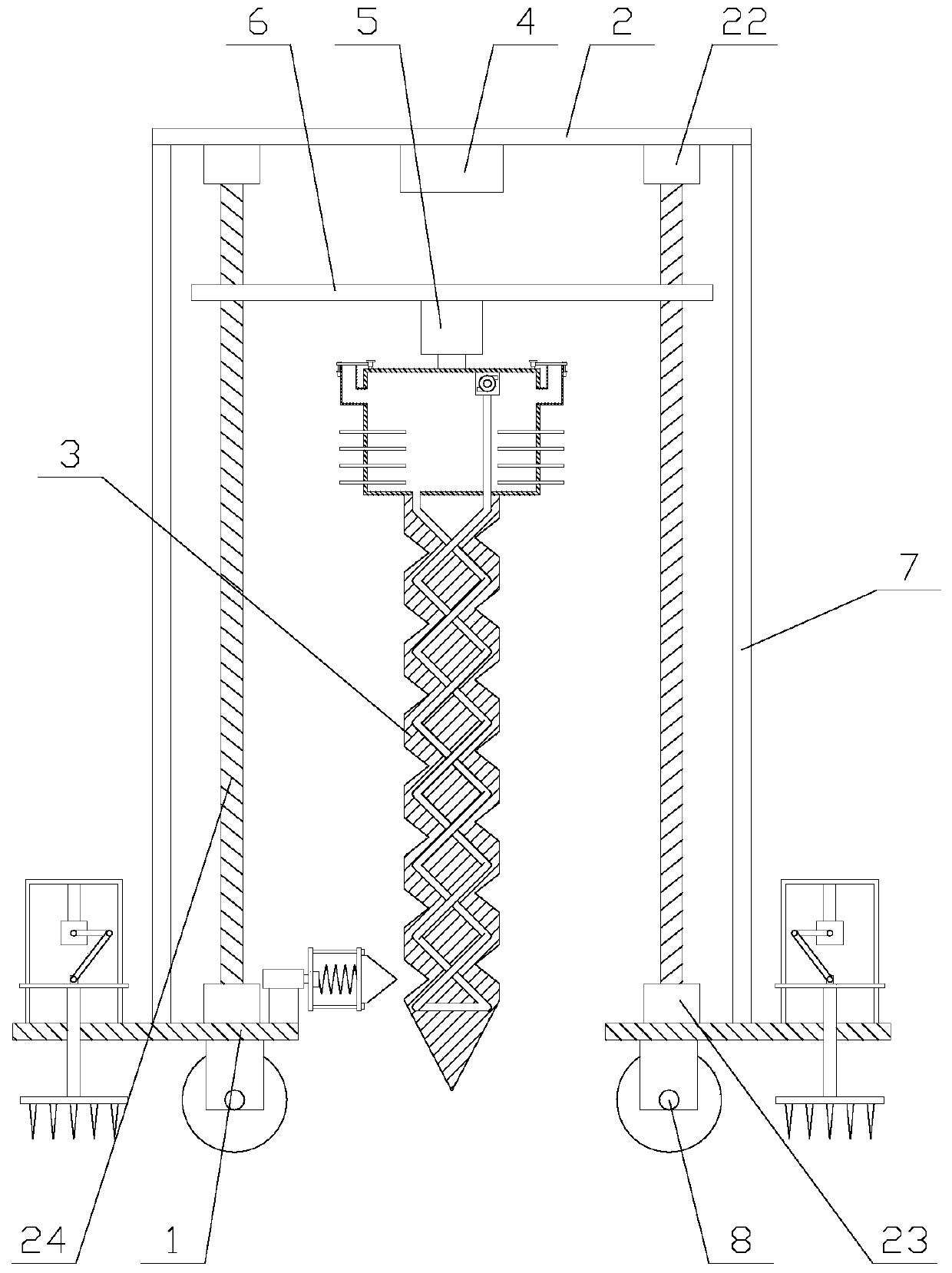
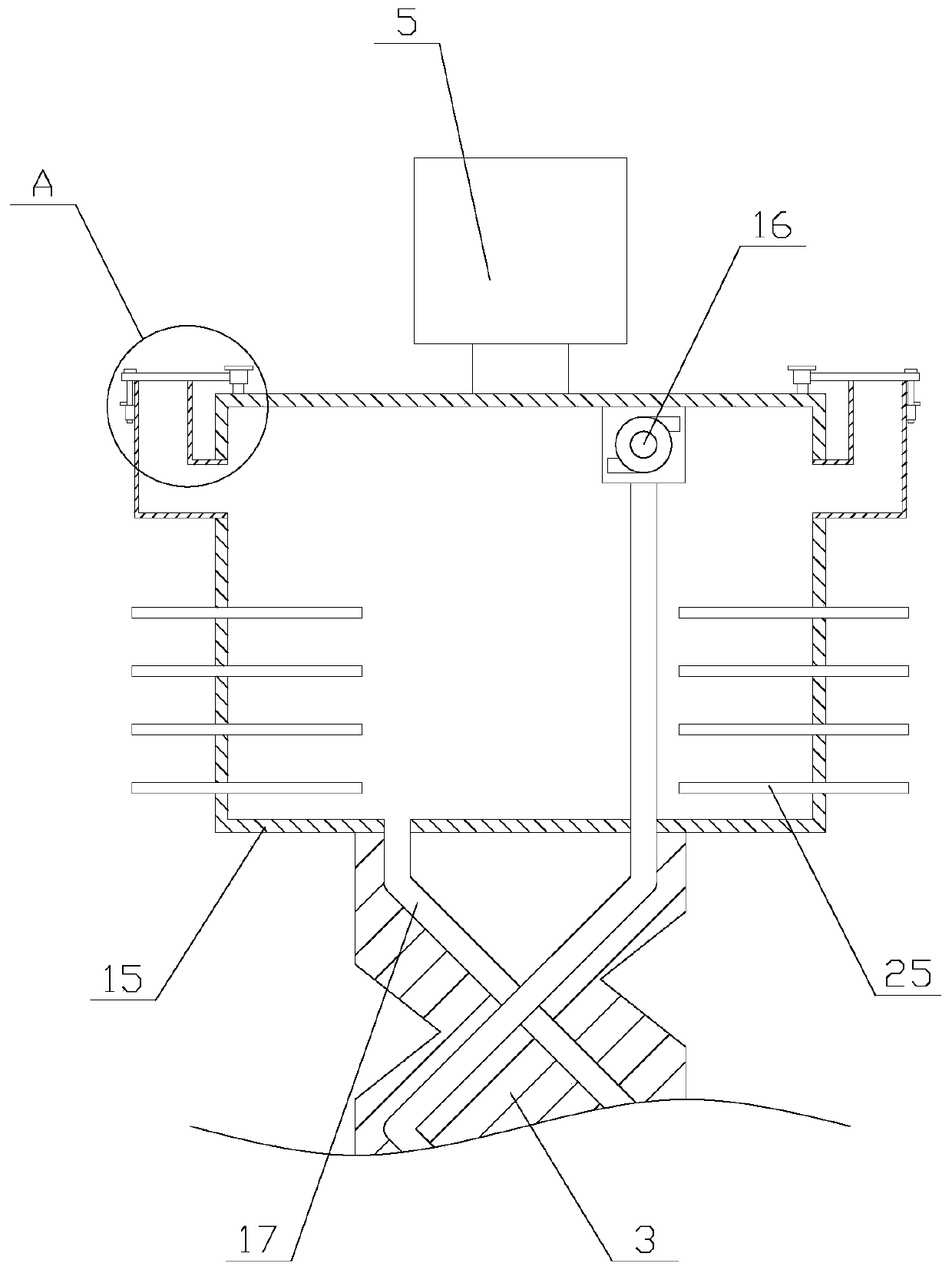
[0026] Such as figure 1 As shown, a down-the-hole drilling machine with a cooling function for mineral mining includes a base 1, a roof 2, a drill pipe 3, a processor 4, a first motor 5, a cooling mechanism, a lifting plate 6, a cleaning mechanism, two A support plate 7 and several rollers 8, the rollers 8 are arranged below the base 1, the support plate 7 is fixed above the base 1, the top plate 2 is erected on two support plates 7, and the processor 4 is fixed Below the top plate 2, the processor 4 is provided with an antenna and a PLC, and the lifting plate 6 is located below the processor 4, and the two ends of the lifting plate 6 are provided with a lift...


PUM


Abstract

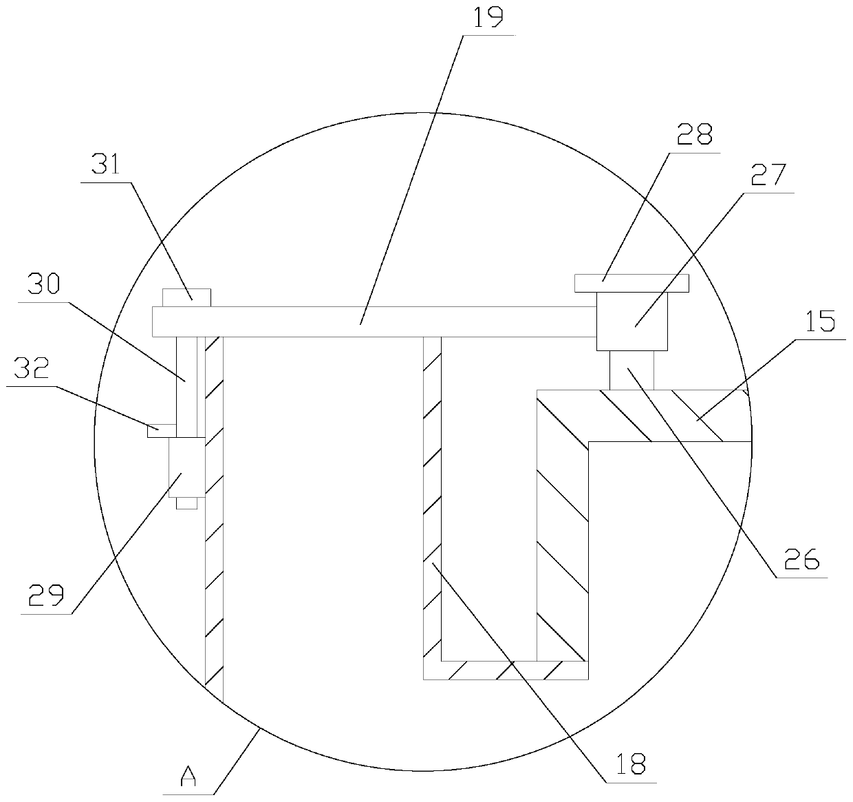
The invention relates to a down-the-hole drill with a cooling function and for mining exploration. The down-the-hole drill comprises a base, a top plate, a drill pipe, a processor, a first motor, a cooling mechanism, a lifting plate, a cleaning mechanism, two supporting plates and a plurality of rollers. The cleaning mechanism comprises a cylinder, a moving plate, a pressure sensor, a spring, a flat plate, a cleaning block and two limiting units. The cooling mechanism comprises a water tank, a water pump, a cooling pipe and two water injection components, and the water injection components comprise water injection pipes, sealing plates, fixing units and rotating units. The down-the-hole drill with the cooling function and for mining exploration enables circulating flowing water to flow through a cooling pipe through the cooling mechanism, the heat of the drill pipe is continuously absorbed, the cooling process of the drill pipe is convenient, and the service life of the drill pipe is prolonged; and moreover, the cleaning mechanism is used for extending a cleaning block into a spiral concave groove of the drill pipe which moves upwards, soil in the spiral concave groove is extruded, the cleaning of the drill pipe is realized, and the practicability of the device is improved.

Description

technical field [0001] The invention relates to the field of mineral mining equipment, in particular to a down-the-hole drilling machine with cooling function for mineral mining. Background technique [0002] The down-the-hole drilling rig is an impact rotary drilling rig. Its internal structure is generally different from that of a rock drill. Its gas distribution and piston reciprocating mechanism are independent, that is, the impactor. The front end is directly connected to the drill bit, and the rear end is connected to the drill pipe. In the hole, through the gas distribution device (valve), the piston (hammer) in the impactor reciprocates and hits the drill tail, so that the drill bit impacts the rock at the bottom of the hole, and the high-speed rotation of the impactor in the hole is controlled by a separate The slewing mechanism is realized by a motor or a pneumatic rotating device outside the hole through a drill pipe connected to the rear end of the impactor. [...

Claims


Application Information

Patent Timeline
IPC IPC(8): E21B4/04E21B12/00E21B12/06E21B17/22
CPCE21B4/04E21B12/00E21B12/06E21B17/006E21B17/22
Inventor 刘志海
Owner 江门市新会区泰盛石场有限公司
Learn More