New-energy constant-temperature house

A new energy and housing technology, applied in building components, buildings, building structures, etc., can solve the problems of wasting manpower and material resources, high energy consumption, etc. Effect

Inactive Publication Date: 2019-09-27
长沙千秋钢结构工程有限公司
View PDF11 Cites 0 Cited by
  • Summary
  • Abstract
  • Description
  • Claims
  • Application Information

AI Technical Summary

Problems solved by technology

[0002] Generally speaking, conventional energy refers to energy that is technically mature and has been used on a large scale, while new energy usually refers to energy that has not yet been used on a large scale and is being actively researched and developed; therefore, coal, oil, natural gas, and large and medium-sized hydropower They are all regarded as conventional energy sources, and solar energy, wind energy, modern biomass energy, geothermal energy, ocean energy and hydrogen energy are regarded as new energy sources; with the rapid development of the economy, energy and environmental problems are becoming more and more serious. The establishment of the concept of sustainable development has made people pay more and more attention to the utilization of new energy. The existing technologies of light, wind and water are basically used for power generation, and then run various electrical appliances through electricity to make people's lives comfortable. In this conversion A lot of manpower and material resources are wasted in the process; for example, through light, wind and water power generation, air conditioners and fans are installed in traditional reinforced concrete houses to make the houses reach a more comfortable temperature. This method consumes a lot of energy and requires further improvement

Method used


Image

  • New-energy constant-temperature house
  • New-energy constant-temperature house
  • New-energy constant-temperature house

Examples


Embodiment Construction

[0016] The specific implementation of the present invention will be further described in detail below in conjunction with the examples.

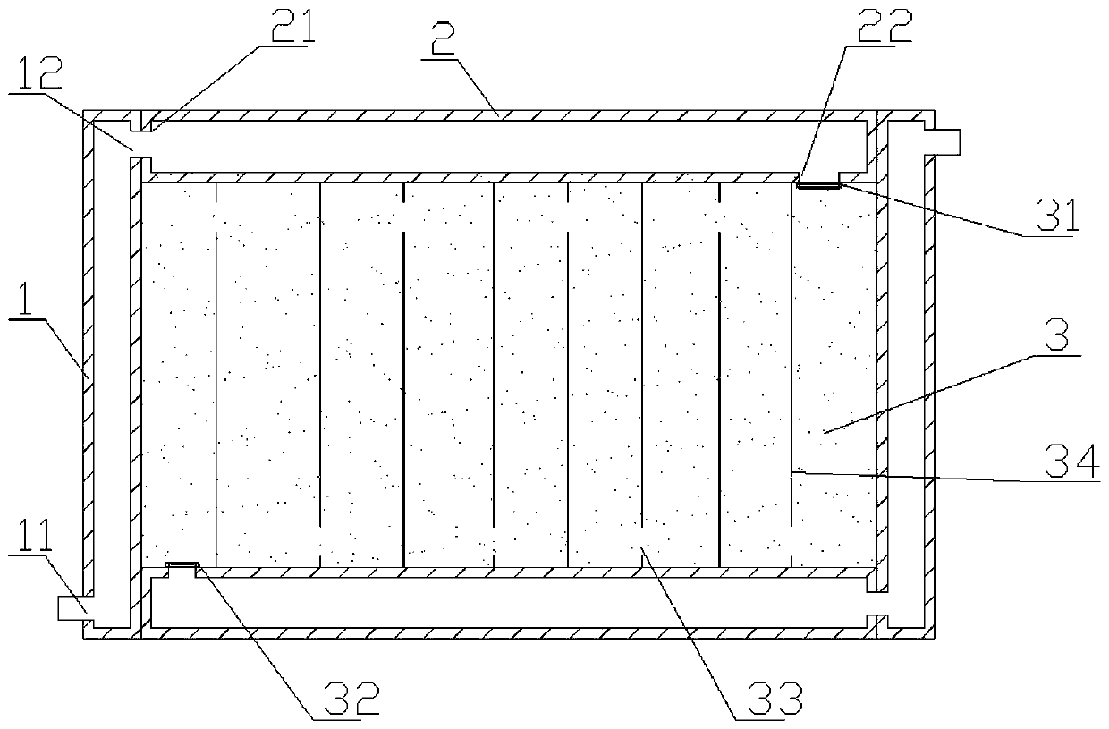
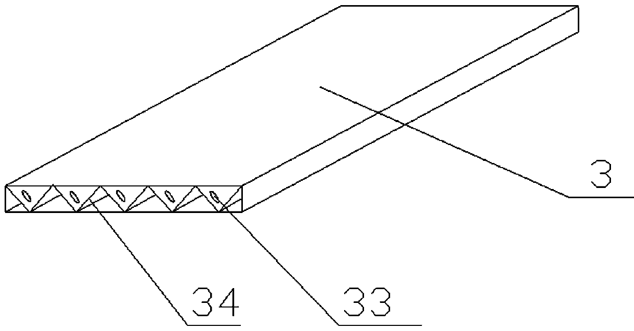
[0017] see Figure 1-3 , the present invention includes a siphon water inlet pipe 4, a siphon water outlet pipe 5, and a house body 6, which is characterized in that the house body 6 is assembled and connected by hollow columns 1, beams 2, and walls 3, and the hollow part of the house body Connected into a group of sealed passages, one end of the passage communicates with the upstream of the river through the siphon water inlet pipe 4, and the other end of the passage communicates with the downstream of the river through the siphon water outlet pipe 5.

[0018] The column 1 is a hollow column. A first communication port 11 is provided on one side of the column, and a second communication port 12 is provided on any one of the three sides of the other end.

[0019] The beam 2 is a hollow beam, the top of one end of the beam is provided with a...


PUM


Abstract

The invention discloses a new-energy constant-temperature house which comprises a siphon water inlet pipe, a siphon water outlet pipe and a house body. The new-energy constant-temperature house is characterized in that the house body is formed by splicing and connecting hollow upright columns, hollow beams and hollow wall bodies, the hollow parts of the house body communicate to form a set of sealed channel, one end of the channel communicates with the upstream of a river through the siphon water inlet pipe, and the other end of the channel communicates with the downstream of the river through the siphon water outlet pipe. The wall bodies, the beams and the upright columns of the house are made to be hollow in advance in a factory, connecting joints are designed at the connecting positions of the parts, one or more sets of sealed channels are formed between the parts after the parts are installed, water of rivers or brooks flows through the interiors of the wall bodies, the beams and the upright columns of the house through a siphon method, the temperature of the house can be slowly consistent with the temperature of the water flow, and the constant-temperature effect is achieved by adjusting the temperature through water.

Description

technical field [0001] The invention relates to a constant temperature house, in particular to a new energy constant temperature house. Background technique [0002] Generally speaking, conventional energy refers to energy that is technically mature and has been used on a large scale, while new energy usually refers to energy that has not yet been used on a large scale and is being actively researched and developed; therefore, coal, oil, natural gas, and large and medium-sized hydropower They are all regarded as conventional energy sources, and solar energy, wind energy, modern biomass energy, geothermal energy, ocean energy and hydrogen energy are regarded as new energy sources; with the rapid development of the economy, energy and environmental problems are becoming more and more serious. The establishment of the concept of sustainable development has made people pay more and more attention to the utilization of new energy. The existing technologies of light, wind and wate...

Claims


Application Information

Patent Timeline
Patent Type & Authority Applications(China)
IPC IPC(8): E04B1/00E04C2/52
CPCE04B1/0023E04C2/521
Inventor 马启义
Owner 长沙千秋钢结构工程有限公司
Why Eureka
Try Eureka