
Load margin calculation method and system for electrical coupling system based on continuous multi-energy flow

A technology of electrical coupling and system load, applied in computing, electrical components, AC network circuits, etc., can solve problems such as improper operation constraint results and failure to consider primary energy supply

Active Publication Date: 2019-09-24
ELECTRIC POWER RES INST OF STATE GRID ZHEJIANG ELECTRIC POWER COMAPNY
View PDF5 Cites 3 Cited by
  • Summary
  • Abstract
  • Description
  • Claims
  • Application Information

AI Technical Summary

Problems solved by technology

[0007] The purpose of the present invention is to provide a method and system for calculating the load margin of an electrical coupling system based on continuous multi-energy flow, so as to solve the problem that the traditional load margin calculation does not consider the primary energy supply of NGU and the operating constraints of the natural gas system. Improper problem, realize accurate calculation of power system load margin under the background of deep coupling of power system and natural gas system, to optimize online evaluation of system static stability, and improve the ability of static stability analysis of electrical coupling system

Method used


Image

  • Load margin calculation method and system for electrical coupling system based on continuous multi-energy flow
  • Load margin calculation method and system for electrical coupling system based on continuous multi-energy flow
  • Load margin calculation method and system for electrical coupling system based on continuous multi-energy flow

Examples


Embodiment 1

[0076] This embodiment provides a method for calculating the load margin of an electrical coupling system based on continuous multi-energy flow, which includes:

[0077] Step 1: Establish a multi-energy flow model considering the safety constraints of the electrically coupled system

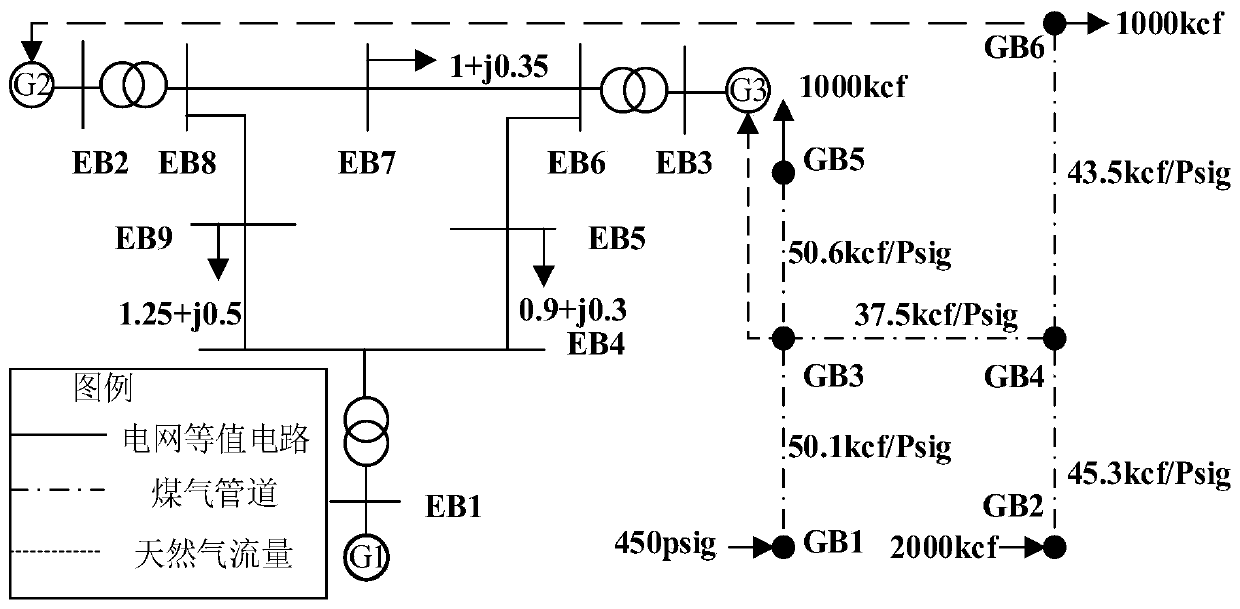
[0078] For a typical IEGS, the electricity system and the natural gas system are coupled together through a gas unit. Firstly, the multi-energy flow models of electric power system, natural gas system and gas-fired unit and the safety constraints of the system are given.

[0079] 1) Natural gas system model

[0080] The node variables of the natural gas system include the flow rate of injected natural gas and the node air pressure. Like the node classification of the power system, nodes can be divided into nodes with known pressure and nodes with known injection flow rate according to known variables. In a natural gas system, the gas source is a balance node, whose gas pressure is known but the...

Embodiment 2

[0139] This embodiment provides a load margin calculation system for an electrical coupling system based on continuous multi-energy flow, which includes:

[0140] The multi-energy flow model establishment unit is used to establish the multi-energy flow model considering the safety constraints of the electrical coupling system, including the multi-energy flow model of the natural gas system model, the electrical system model and the gas generating set model;

[0141] The formation unit of multi-energy flow calculation method: imitating the continuous power flow, introducing load growth parameters to form a continuous multi-energy flow calculation method;

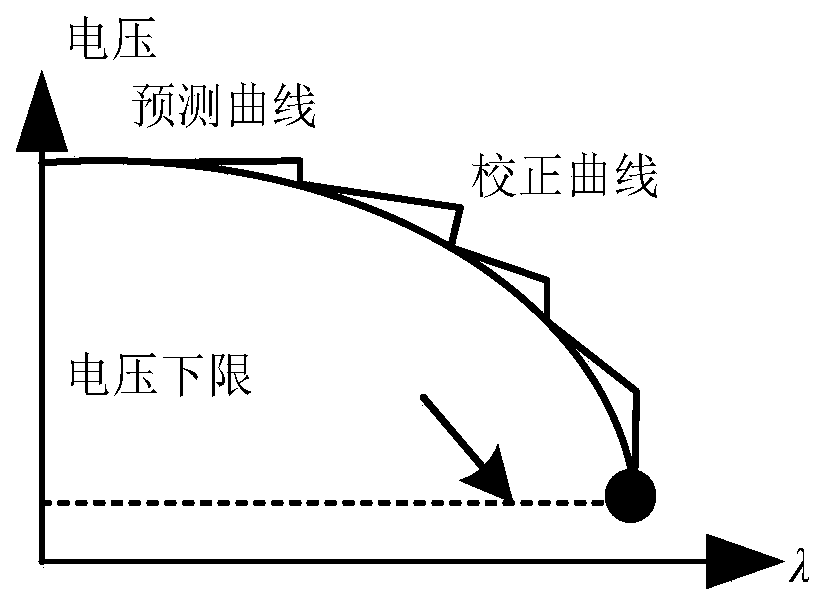
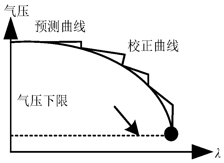
[0142] System load margin calculation unit: The continuous multi-energy flow calculation method is used to track the multi-energy flow solution curve and calculate the system load margin.


PUM


Abstract

The invention discloses a load margin calculation method and system for an electrical coupling system based on continuous multi-energy flow. The conventional load margin calculation does not consider the primary energy supply of a gas generator set and the operation constraint of a natural gas system. The technical scheme comprises the following steps: establishing a multi-energy flow model considering the safety constraint of the electrical coupling system, including the multi-energy flow model of the natural gas system, a power system and the gas generator set; and proposing a continuous multi-energy flow calculation method to solve the relation curve between the node pressure of a gas network, the node voltage of a power network and the load margin based on the continuous power flow and the load growth parameters so as to calculate the system load margin. According to the method, the load margin of the electrical coupling system can be determined and the influence of the safety constraint of the natural gas system on the load margin can be analyzed so as to provide the reference for adjustment of the operation state of the natural gas system and have an important significance for the online evaluation of the system static stability and is helpful for the system dispatcher to monitor the operation stability of the system.

Description

technical field [0001] The invention belongs to the technical field of power system voltage stability index optimization, and in particular relates to a load margin calculation method and system for an electrical coupling system based on continuous multi-energy flow. Background technique [0002] In recent years, the share of natural gas-fired units (NGUs) in the power system has been continuously increasing due to their good economy, fast adjustment ability and low pollution emission characteristics. With the rapid increase of the power generation share of gas-fired units, electric power systems (EPSs) and natural gas systems (NGSs) have gradually formed a unified integrated system-electrically coupled system (IEGS). Therefore, as the coupling becomes tighter, the interaction effects between different energy supply systems should be closely monitored. [0003] At present, relevant research work on IEGS has been carried out at home and abroad: some studies use P2G technolog...

Claims


Application Information

Patent Timeline
Patent Type & Authority Applications(China)
IPC IPC(8): H02J3/00G06Q50/06
CPCH02J3/00G06Q50/06H02J2203/20
Inventor 李志浩倪筹帷汪湘晋林达赵波
Owner ELECTRIC POWER RES INST OF STATE GRID ZHEJIANG ELECTRIC POWER COMAPNY
Learn More