Capacitive electromagnetic flowmeter
An electromagnetic flowmeter, capacitive technology, applied in the application of electromagnetic flowmeter to detect fluid flow, volume/mass flow generated by electromagnetic effects, measurement flow/mass flow, etc., can solve the problem of high impedance and the sensitivity of the initial signal amplification circuit to noise Influence, electromagnetic flowmeter measurement accuracy and measurement stability decrease, etc., to achieve the effect of reducing costs and suppressing temperature drift
- Summary
- Abstract
- Description
- Claims
- Application Information
AI Technical Summary
Problems solved by technology
Method used
Image

Examples
no. 1 Embodiment approach
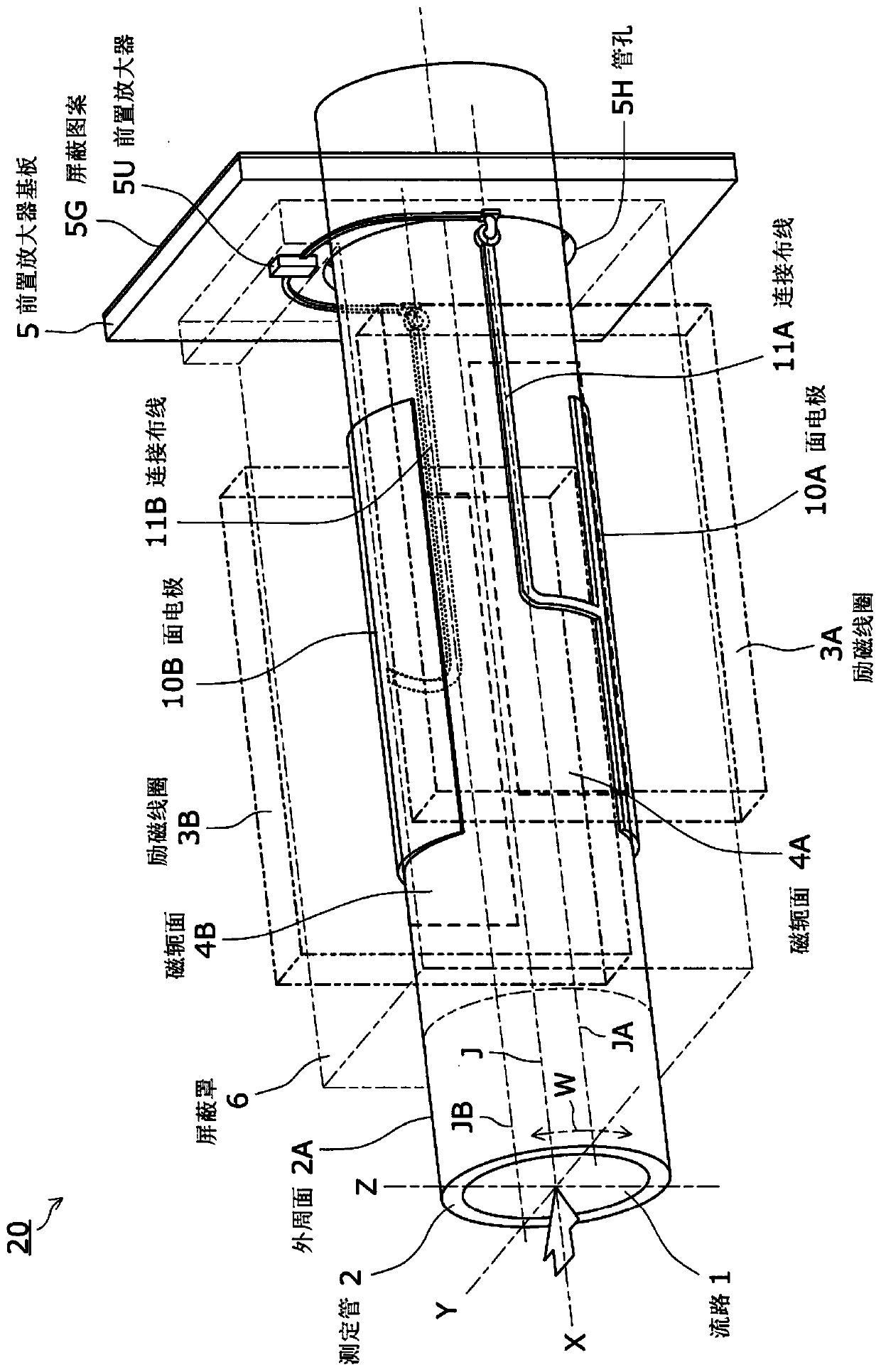
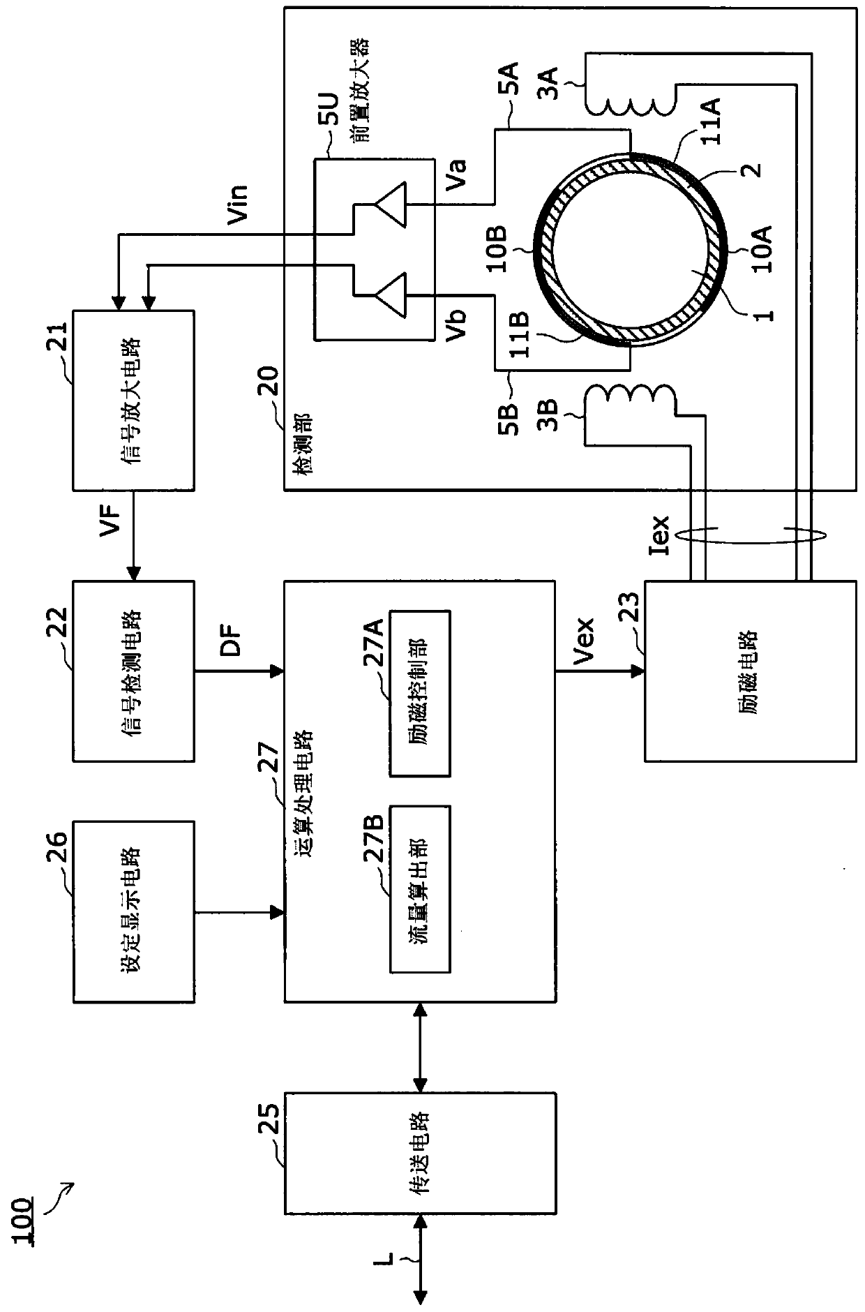
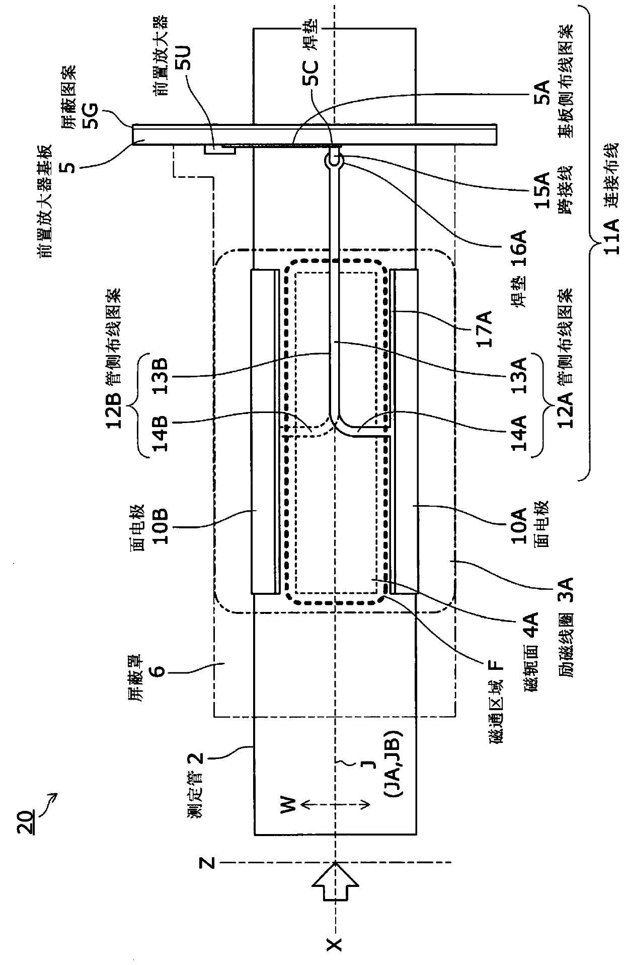
[0057] First, refer to figure 1 as well as figure 2 , the capacitance type electromagnetic flowmeter 100 according to the first embodiment of the present invention will be described. figure 1 It is a perspective view showing the detecting part of the capacitance type electromagnetic flowmeter of the first embodiment. figure 2 It is a block diagram showing the circuit configuration of the capacitance type electromagnetic flowmeter of the first embodiment.
[0058] [Capacitance Electromagnetic Flowmeter]
[0059] This capacitive electromagnetic flowmeter 100 has the following function: using the electrodes provided on the outer peripheral surface of the measuring tube, through the electrostatic capacitance between the fluid and the electrodes, the flow of the measuring object flowing in the measuring tube due to the magnetic flux applied by the exciting coil is performed. The electromotive force generated in the fluid is detected, and the resulting electromotive force is ...
no. 2 Embodiment approach
[0114] Next, refer to Figure 7 , a capacitance type electromagnetic flowmeter according to a second embodiment of the present invention will be described. Figure 7 It is a front view of the detection part of 2nd Embodiment.
[0115] In the first embodiment, as a method of mounting the preamplifier substrate 5 to the measuring tube 2, the outer peripheral surface 2A of the measuring tube 2 passing through the tube hole 5H and the end of the tube hole 5H are fixed with an adhesive. An example is described. In this embodiment, the case where the preamplifier board 5 is mounted by pressure welding the end of the tube hole 5H to the outer peripheral surface 2A of the measuring tube 2 will be described.
[0116] Such as Figure 7 As shown, the preamplifier substrate of the present embodiment may be provided with a convex portion 5T on the hole wall surface of the tube hole 5H, and the convex portion 5T is in contact with the outer peripheral surface 2A. As a result, the end of...
no. 3 Embodiment approach
[0120] Next, refer to Figure 8 ~ Figure 10 The detecting unit 20 of the capacitance type electromagnetic flowmeter 100 according to the third embodiment of the present invention will be described. Figure 8 It is a plan view of the detection unit of the third embodiment. Figure 9 It is a side view of the detection part of 3rd Embodiment. Figure 10 It is a front view of the detection part of 3rd Embodiment.
[0121] In the first embodiment, the case where the front electrodes 10A, 10B, the connection wirings 11A, 11B, and the preamplifier 5U are collectively shielded by one shield case 6 has been described as an example. In this embodiment, a case where the preamplifier 5U, the surface electrodes 10A, 10B, and the connection wirings 11A, 11B are individually shielded will be described.
[0122] That is, if Figure 8 ~ Figure 10 As shown, the detection unit 20 of this embodiment includes two shields 6A, 6B, the shielding case 6A shields the facing electrodes 10A, 10B and ...
PUM
 Abstract
Description
Claims
Application Information
 - R&D
- Intellectual Property
- Life Sciences
- Materials
- Tech Scout
- Unparalleled Data Quality
- Higher Quality Content
- 60% Fewer Hallucinations
Browse by: Latest US Patents, China's latest patents, Technical Efficacy Thesaurus, Application Domain, Technology Topic, Popular Technical Reports.
© 2025 PatSnap. All rights reserved.Legal|Privacy policy|Modern Slavery Act Transparency Statement|Sitemap|About US| Contact US: help@patsnap.com