
A laser processing device based on two coaxial ccds for visual positioning

A visual positioning and laser processing technology, applied in metal processing equipment, laser welding equipment, manufacturing tools, etc., can solve the problems of high cost, low work efficiency, complex structure of moving mechanism, etc., to achieve low cost, work efficiency improvement, precision high effect

Active Publication Date: 2021-11-05
南理工泰兴智能制造研究院有限公司
View PDF10 Cites 0 Cited by
  • Summary
  • Abstract
  • Description
  • Claims
  • Application Information

AI Technical Summary

Problems solved by technology

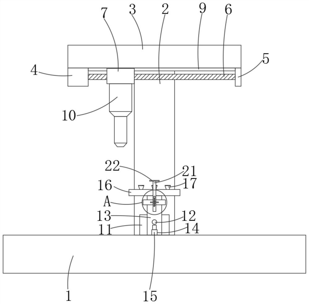
[0004] The purpose of the present invention is to solve the shortcomings in the prior art, such as: the existing laser processing device based on two coaxial CCDs for visual positioning needs to control the laser cutting device along the The position adjustment of the laser cutting device can only be completed by moving the plane vertically and horizontally, so that the laser cutting device can be positioned directly above the workpiece. However, the existing moving mechanism of the laser cutting device has a complex structure, high cost, and low work efficiency. Moreover, the existing laser cutting device cannot achieve a good positioning effect on cylindrical and round tube workpieces, so the accuracy of laser processing is low

Method used


Image

  • A laser processing device based on two coaxial ccds for visual positioning
  • A laser processing device based on two coaxial ccds for visual positioning
  • A laser processing device based on two coaxial ccds for visual positioning

Examples


Embodiment Construction

[0020] The following will clearly and completely describe the technical solutions in the embodiments of the present invention with reference to the accompanying drawings in the embodiments of the present invention. Obviously, the described embodiments are only some, not all, embodiments of the present invention.

[0021] In describing the present invention, it should be understood that the terms "upper", "lower", "front", "rear", "left", "right", "top", "bottom", "inner", " The orientation or positional relationship indicated by "outside", etc. is based on the orientation or positional relationship shown in the drawings, and is only for the convenience of describing the present invention and simplifying the description, rather than indicating or implying that the referred device or element must have a specific orientation, so as to Specific orientation configurations and operations, therefore, are not to be construed as limitations on the invention.

[0022] refer to Figure ...


PUM


Abstract

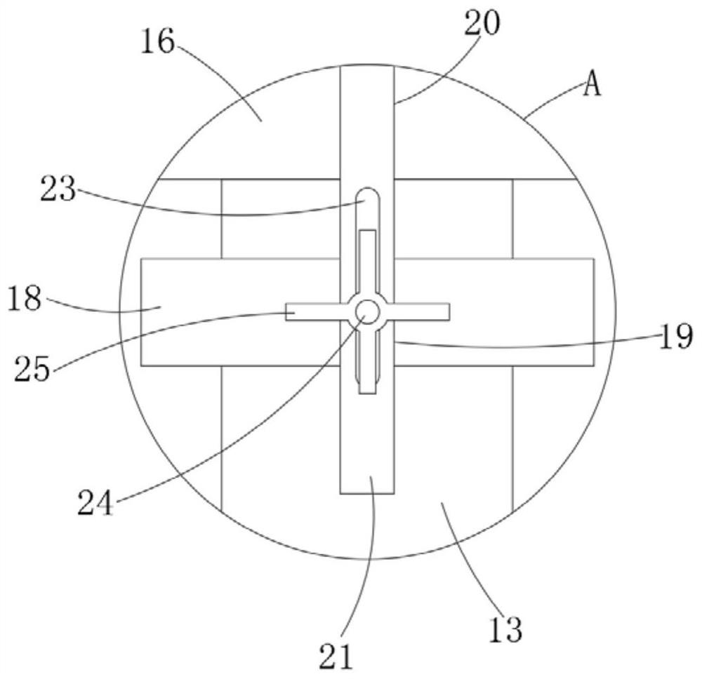
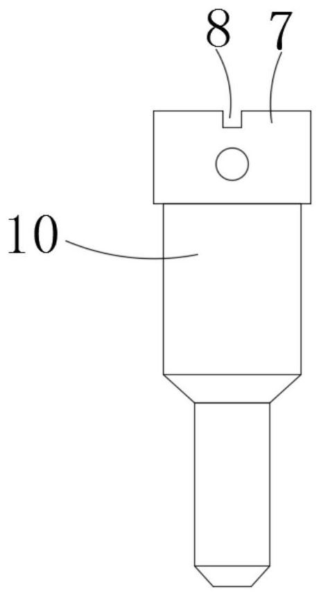
The invention discloses a laser processing device for visual positioning based on two coaxial CCDs, which includes a workbench, a support rod is fixedly connected to the upper end surface of the workbench, and the end of the support rod far away from the workbench is fixedly connected There is a top plate, and a first stepper motor is fixedly connected to the bottom side wall of the top plate. The present invention can not only quickly locate plate-shaped workpieces and flat sidewall workpieces, but also play a good role in fixing and limiting workpieces such as round tubes and cylinders, and is applicable to workpieces of different radial sizes. It is driven by two sets of separate one-way moving mechanisms, and the rapid positioning of the laser cutting device to the workpiece is realized through the cooperation of the two, so the precision of laser processing is very high, and the cost is low. In addition, due to the first stepping motor and The second stepper motor can work simultaneously and cooperate with each other, so the work efficiency of laser processing has been greatly improved.

Description

technical field [0001] The invention relates to the technical field of laser processing devices, in particular to a laser processing device for visual positioning based on two coaxial CCDs. Background technique [0002] Laser processing has become an important processing method in modern manufacturing, especially in the fields of precision processing and micro-processing. Laser processing has been widely used in microelectronics, liquid crystal, separation membrane, measurement, automobile, aviation, nanomaterials, aerospace and other fields. With the development of science and technology, modern precision manufacturing has higher and higher requirements for the shape and position accuracy, flexibility, adaptability, intelligence and efficiency of laser processing. Laser processing devices with low requirements have no visual positioning function, and laser processing devices with high requirements usually have a visual positioning system based on two coaxial CCDs. [0003]...

Claims


Application Information

Patent Timeline
Patent Type & Authority Patents(China)
IPC IPC(8): B23K26/38B23K26/03B23K26/08B23K26/70
CPCB23K26/032B23K26/0876B23K26/38B23K26/702
Inventor 张奕
Owner 南理工泰兴智能制造研究院有限公司
Learn More