
Gas-liquid separation device

A technology of gas-liquid separation device and liquid inlet, which is applied in the direction of separation method, liquid degassing, liquid degassing adjustment/control, etc. It can solve the problems of inability to ensure the continuity of chemical transmission and complex structure, and achieve simple structure, Guaranteed continuity of effect

Inactive Publication Date: 2019-09-24
BEIJING SEMICON EQUIP INST THE 45TH RES INST OF CETC
View PDF5 Cites 0 Cited by
  • Summary
  • Abstract
  • Description
  • Claims
  • Application Information

AI Technical Summary

Problems solved by technology

[0004] The purpose of the present invention is to provide a gas-liquid separation device to alleviate the technical problems that the structure of the gas-liquid separation device used in the chemical transportation process in the prior art is relatively complex and cannot ensure the continuity of chemical transportation

Method used


Image

  • Gas-liquid separation device

Examples


Embodiment Construction

[0026] The technical solutions of the present invention will be clearly and completely described below in conjunction with the accompanying drawings. Apparently, the described embodiments are some of the embodiments of the present invention, but not all of them. Based on the embodiments of the present invention, all other embodiments obtained by persons of ordinary skill in the art without making creative efforts belong to the protection scope of the present invention.

[0027] In the description of the present invention, it should be noted that the terms "center", "upper", "lower", "left", "right", "vertical", "horizontal", "inner", "outer" etc. The indicated orientation or positional relationship is based on the orientation or positional relationship shown in the drawings, and is only for the convenience of describing the present invention and simplifying the description, rather than indicating or implying that the referred device or element must have a specific orientation, ...


PUM


Abstract

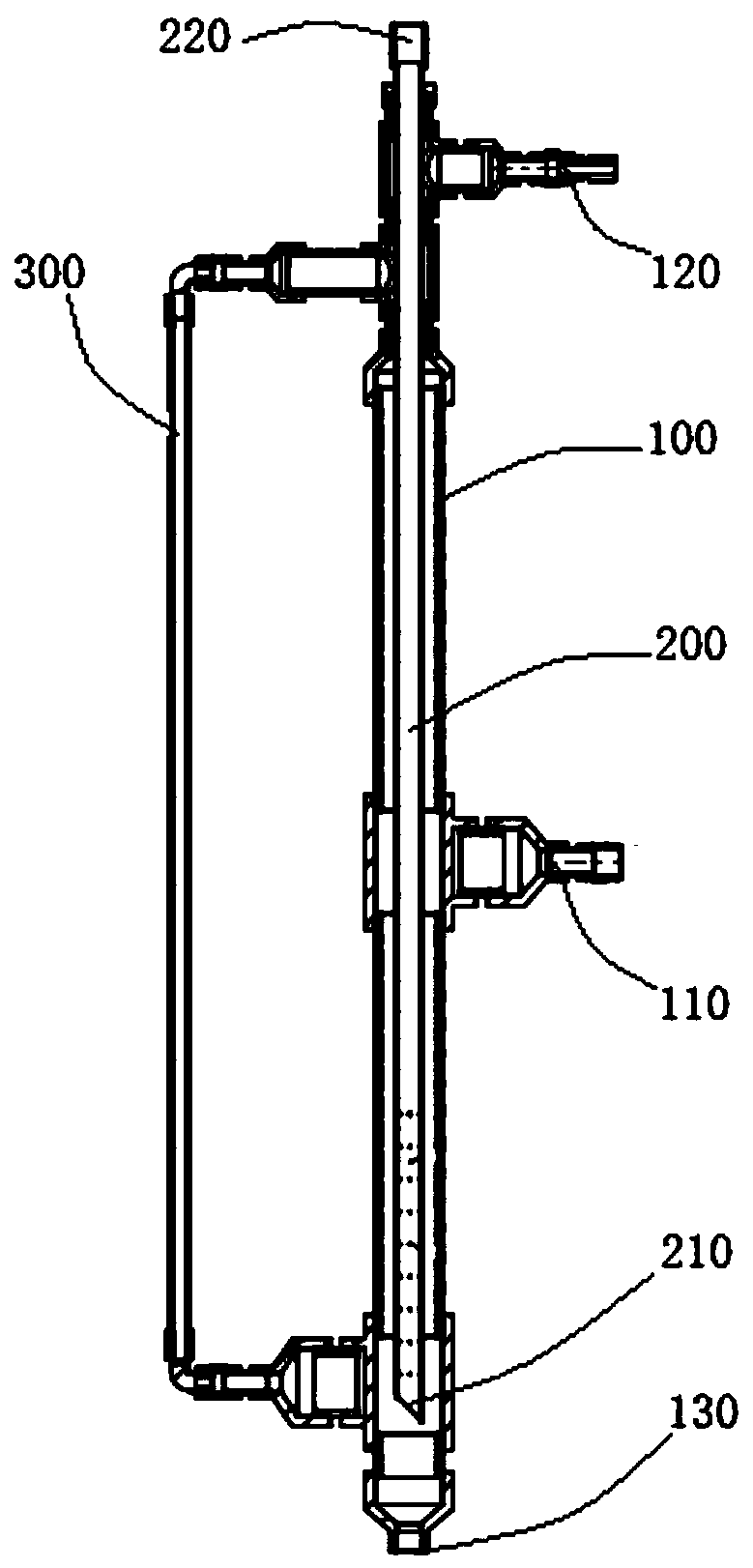
The invention provides a gas-liquid separation device, and relates to the technical field of gas-liquid separation. The gas-liquid separation device comprises an outer tube and an inner tube, the upper end of the outer tube is provided with a first opening for inserting the inner tube, and when the inner tube is inserted into the outer tube to a specified depth, the inner tube is in sealed connection with the outer tube at the first opening; the outer tube is further provided with a first liquid inlet and a gas outlet for discharging gas separated from a liquid, a first switching valve is installed at the gas outlet, and the first switching valve is in a normally closed state; and the lower end of the inner tube is provided with a second liquid inlet, the inner tube communicates with the outer tube through the second liquid inlet, the part, located outside the outer tube, of the inner tube is provided with a liquid outlet, and the liquid from which the gas is separated is discharged from the liquid outlet. The device provided by the invention alleviates the technical problems that a gas-liquid separation device used in a chemical conveying process in the prior art has a complicated structure and cumbersome installation and cannot ensure continuity of chemical conveying.

Description

technical field [0001] The invention relates to the technical field of gas-liquid separation, in particular to a gas-liquid separation device. Background technique [0002] As automatic wet chemical equipment is more and more widely used in semiconductor, solar energy, LED and other fields, the demand is increasing. Traditional manual liquid preparation and replenishment are gradually replaced by automatic liquid supply. During this process, chemicals Centralized liquid supply system has been more and more important application. Especially in the use environment such as large-lift conveying and precise proportioning, it shows its great advantages. According to actual needs, it is very important to be able to ensure continuous and accurate liquid supply. In actual operation, because the chemical liquid itself will contain a small amount of air bubbles, and the operation of changing the barrel during the liquid supply process will increase the gas in the pipeline, resulting ...

Claims


Application Information

Patent Timeline
Patent Type & Authority Applications(China)
IPC IPC(8): B01D19/00
CPCB01D19/0063
Inventor 袁恋夏楠君赵宝君吴娖张伟锋
Owner BEIJING SEMICON EQUIP INST THE 45TH RES INST OF CETC
Learn More