Backlight module and display device

A backlight module and metal backplane technology, applied in optics, nonlinear optics, instruments, etc., can solve problems such as uneven backlight illumination and inconsistent light mixing distance

Active Publication Date: 2019-09-20
XIAMEN TIANMA MICRO ELECTRONICS
View PDF8 Cites 7 Cited by
  • Summary
  • Abstract
  • Description
  • Claims
  • Application Information

AI Technical Summary

Problems solved by technology

However, the backplane and the light board of the backlight module are not integrally formed, so the light board and the backplane are often not tightly bonded together, especially in curved display devices, the light board cannot be completely attached to the backplane due to its own stress. This causes the light mixing distance of the light source at this position to be inconsistent with the light mixing distance of other light sources due to the lack of tight fit in some positions, resulting in the problem of uneven backlight illumination.

Method used


Image

  • Backlight module and display device
  • Backlight module and display device
  • Backlight module and display device

Examples


Embodiment Construction

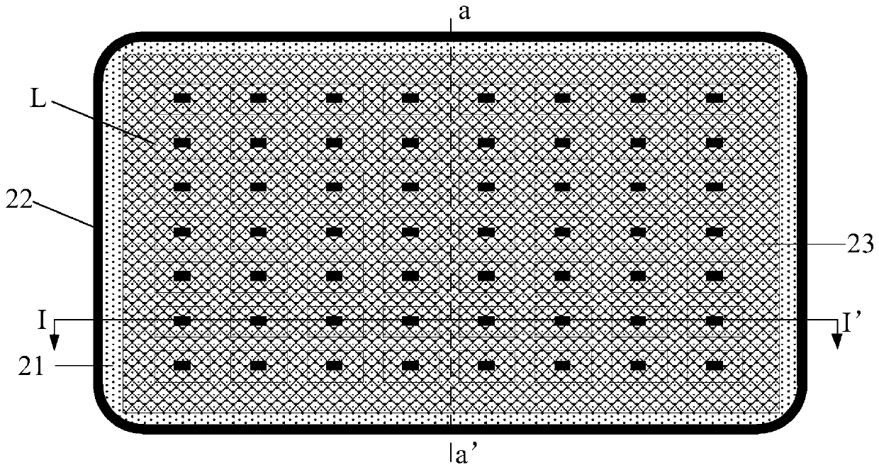
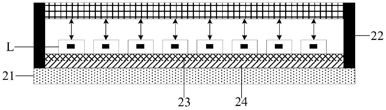
[0038] In order to make the above objects, features and advantages of the present invention more comprehensible, the present invention will be further described below in conjunction with the accompanying drawings and embodiments. Example embodiments may, however, be embodied in many forms and should not be construed as limited to the embodiments set forth herein; rather, these embodiments are provided so that this disclosure will be thorough and complete, and will fully convey the concept of example embodiments to those skilled in the art. The same reference numerals denote the same or similar structures in the drawings, and thus their repeated descriptions will be omitted. The words expressing position and direction described in the present invention are all described by taking the accompanying drawings as an example, but changes can also be made according to needs, and all changes are included in the protection scope of the present invention. The drawings of the present inv...


PUM


Abstract

The invention discloses a backlight module and a display device. The backlight module comprises a metal back plate, and a plastic frame arranged around the edges of the metal back plate, wherein an accommodating space is formed by the metal back plate and the plastic frame. The backlight module further comprises a lamp board, wherein the lamp board is positioned on one side of the metal back plate, and is arranged in the accommodating space; the surface of one side, facing the metal back plate, of the lamp board is provided with a first magnetic material layer; and the first magnetic material layer is adsorbed to the metal back plate. The metal back plate is generally made of an iron or iron alloy material, and the magnetic material has the property of attracting magnetic metal. When the lamp board is mounted in the accommodating space formed by the metal back plate and the plastic frame, the first magnetic material layer can be directly adsorbed onto the metal back plate. The metal back plate and an optical film of the backlight module are arranged in parallel, and the lamp board is closely attached to the metal back plate to ensure that the light mixing distances from light sources at all positions on the lamp board to the optical film are kept uniform, thereby improving light mixing uniformity of the light sources on the lamp board and making the emergent light of the backlight module more uniform.

Description

technical field [0001] The invention relates to the field of display technology, in particular to a backlight module and a display device. Background technique [0002] With the development of display technology, display screens have penetrated into all aspects of people's lives as information displays. Among them, liquid crystal display technology research is mature, and liquid crystal displays have been widely used in various application scenarios. Since the liquid crystal display is a non-self-illuminating device, it needs to provide a backlight source through a backlight module to realize the display function. A backlight module usually includes multiple light sources. In order to make the light incident on the display panel more uniform, the light mixing distance of each light source is required to be the same. However, the backplane and the light board of the backlight module are not integrally formed, so the light board and the backplane are often not tightly bonded...

Claims


Application Information

Patent Timeline
IPC IPC(8): G02F1/13357
CPCG02F1/133603G02F1/133608G02F1/133611
Inventor 唐明李植强
Owner XIAMEN TIANMA MICRO ELECTRONICS
Why Eureka
Try Eureka